background image

5

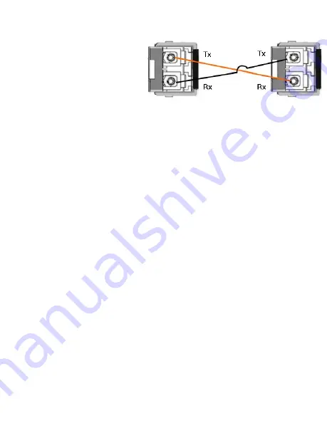
The SFP port does not function until the fiber cable is linked to another active 

device. The SFP and corresponding RJ45 ports work in an exclusive mode.  

Traffic sent or received through 

the SFP module has priority thus 

no traffic is sent or received over 

the corresponding RJ45 

connection.  To use the RJ45 

connection, remove the 

corresponding SFP. 
Multi-Mode cables should not 

exceed 2KM and Single-Mode cables should not exceed 30km.

PROGRAMMING THE IP ADDRESS

Configure the IP address using one of the following methods:

•  PortVision DX (

http://downloads.comtrol.com

)

•  Web browser

•  Telnet

• 

Command line interface (CLI) using the RS-232 console cable

The easiest way to configure a static IP address for your network in 

the ES8510 is to use a Windows host and PortVision DX (see below). 

For information about using other configuration methods, refer to the 

appropriate 

RocketLinx ES8510 User Guide.

The following procedure uses PortVision DX to program network settings. 

1.  Install PortVision DX on a host system with a Windows operating system. 

If you need assistance installing PortVision DX, see the appropriate 

RocketLinx ES8510 User Guide.

2.  Start PortVision DX. PortVision DX can be started from 

Start --> All 

Programs --> Comtrol --> PortVision DX.

3. 

Click the 

Scan

 button.

4.  Select the Comtrol product families that you want to locate and click the 

Scan

 button. 

5. 

Right-click the ES8510 in the 

Device List

 pane (lower) that you want to 

configure and click 

Properties

.

6.  Enter a user-friendly Device Name.

7.  Optionally, enter the ES8510 serial number, which displays a friendly 

device name in the 

Device List

 pane on the main page. 

Summary of Contents for ROCKETLINX ES8510

Page 1: ...QUICK INSTALLATION GUIDE 2000515 Rev G Release Date October 2016 ROCKETLINX ES8510 ES8510 ES8510 XT ES8510 XTE ...

Page 2: ...ents ES8510 provides a wide operating temperature ES8510 XT ES8510 XTE are NEMA TS2 certified and provide an extended operating temperature The ES8510 ES8510 XT and ES8510 XTE are referred to as the ES8510 unless there is a difference between the models See the Comtrol website for complete product specifications INSTALLATION OVERVIEW If you need more detailed installation and configuration informa...

Page 3: ...ge ES8510 ES8510 XT 12 to 48VDC ES8510 XTE 10 to 60VDC The Power 1 2 LEDs turn red during the boot cycle and change to green when the ES8510 is ready 3 Tighten the wire clamp screws to prevent the wires from being loosened Wiring the Alarm Relay Output The ES8510 provides two digital inputs and two digital outputs dry relay output on terminal block connectors on the bottom of the unit Fault condit...

Page 4: ...fications 1 Insert the positive and negative wires 12 24 AWG into V and V 2 Tighten the wire clamp screws to prevent the wires from coming loose Mounting the ES8510 You can mount the ES8510 onto a DIN rail or optionally a panel or wall Follow the steps below to install the ES8510 with the wall mounting plate 1 To remove the DIN rail clip from the ES8510 loosen the screws from the DIN rail clip 2 P...

Page 5: ...ffic and link status See the LED subsection for more information Always make sure that the cables between the switches and attached devices for example switch hub or workstation are less than 100 meters 328 feet 10BASE T Category 3 4 or 5 cable 100BASE TX 1000BASE TX Category 5 or 5e cable Connecting the SFP Transceivers To ensure system reliability Comtrol recommends using Comtrol certified SFP t...

Page 6: ...network in the ES8510 is to use a Windows host and PortVision DX see below For information about using other configuration methods refer to the appropriate RocketLinx ES8510 User Guide The following procedure uses PortVision DX to program network settings 1 Install PortVision DX on a host system with a Windows operating system If you need assistance installing PortVision DX see the appropriate Roc...

Page 7: ...access the ES8510 without attaching an admin PC to the network You can also use out bound management if you lost the network connection to the ES8510 In band management means that you connect remotely using the ES8510 IP address through the network You can remotely connect with the ES8510 web interface or a Telnet console and the CLI The following procedure uses a web browser to configure ES8510 f...

Page 8: ... Ring function disabled or ES8510 is on a ring but not the ring master 1 7 Green Linked to another device Amber Full Duplex Green Active traffic Not connected Collision 8 10 SFP RJ45 Green Connected Green Active connection Green Active connection Green Active connection Plugged in but not linked up Not connected COMTROL CUSTOMER SERVICE You can use one of the following methods to contact Comtrol C...

Reviews: