Connecting Serial Devices
DeviceMaster UP User Guide
: 2000451 Rev. C
- 25
Connecting Serial Devices
This section discusses connecting your serial devices. In addition, it provides you
with information to build serial or test cables and loopback connectors to test the
serial ports.
Note:
Building the Serial Ribbon Cable
on Page 21 for connector
information for the DeviceMaster UP 1-Port Embedded adapter.
Connecting Devices
Use this procedure to connect asynchronous serial devices to the DeviceMaster UP
ports.
1.
Connect your serial devices to the appropriate port on the DeviceMaster UP
using the appropriate cable. You can build your own DB9 cables using the
appropriate discussion:
•
DB9 Serial Cables and Loopback Plugs
•
RJ45 Serial Cables and Loopback Plugs
Note:
Refer to the hardware manufacturer’s installation documentation if you
need help with connector pinouts or cabling for the peripheral device.
2.
Verify that the devices are communicating properly.
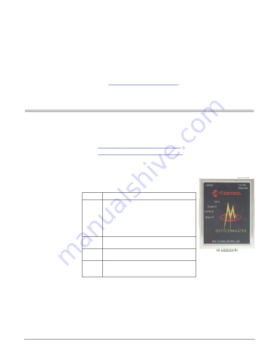
The DeviceMaster UP 1-port has four LEDs on the
top of the unit that provide information about the
network connection of the serial port.
LED
Description
Status
The amber
Status
LED on the device is lit,
indicating you have power and it has
completed the boot cycle.
Note:
The
Status
LED flashes while
booting and it takes approximately
15 seconds for the bootloader to
complete the cycle.
Link Act
If the red
Link Act
LED is lit, it indicates a
working Ethernet connection.
Duplex
If the red
Duplex
LED is lit, it indicates
full-duplex activity.
100
If the red
100
LED is lit, it indicates a
working 100 MB Ethernet connection (100
MB network, only).


