


9
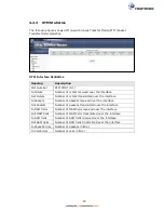
2.2 LED Indicators
The front panel LED indicators are shown below and explained in the following table.
This information can be used to check the status of the device and its connections.
LED
Color
Mode
Function
POWER
GREEN
On
The device is powered up.
Off
The device is powered down.
Blink Software upgrade is being upgraded.
RED
On
POST (Power On Self Test) failure or other
malfunction. A malfunction is any error
of internal sequence or state that will
prevent the device from connecting to the
DSLAM or passing customer data.
PHONE 1
GREEN
On
An FXS port is off hook.
Off
An FXS port is on hook.
PHONE 2
GREEN
On
An FXS port is off hook.
Off
An FXS port is on hook.
ETH WAN
GREEN
On
WAN is connected at 1000 Mbps.
Off
Ethernet WAN is not connected.
Blink In TX/RX over 1000 Mbps
ORANGE
On
Ethernet is connected at 10/100 Mbps.
Off
Ethernet WAN is not connected.
Blink In TX/RX over 10/100 Mbps.
ETH 4 to 1
GREEN
On
Ethernet is connected at 1000 Mbps.
Off
Ethernet is not connected.
Blink In TX/RX over 1000 Mbps.
ORANGE
On
Ethernet is connected at 10/100 Mbps.
Off
Ethernet is not connected.
Blink In TX/RX over 10/100 Mbps.
WPS
GREEN
On
WPS(2.4G) WPS enabled and client
connected to WLAN.
Off
WPS(2.4G) WPS disabled.
Blink WPS(2.4G) WPS connection in progress,
120 seconds or until client connected.
ORANGE
On
WPS(5G WPS enabled and client
connected to WLAN.
Off
WPS(5G) WPS disabled.
Blink WPS(5G) WPS connection in progress,
120 seconds or until client connected.
Summary of Contents for NexusLink 3241eu
Page 1: ...261103 018 NexusLink 3241u 3241eu Bonding IAD User Manual Version A1 0 May 17 2017...
Page 16: ...15 STEP 3 After successfully logging in for the first time you will reach this screen...
Page 63: ...62 A maximum of 100 entries can be added to the URL Filter list...
Page 66: ...65 Click Enable to activate the QoS Queue Click Add to display the following screen...
Page 82: ...81 5 11 DSL Bonding This page displays the bonding status of the connected xDSL line...
Page 83: ...82 5 12 UPnP Select the checkbox provided and click Apply Save to enable UPnP protocol...
Page 103: ...102 Enter a certificate name and click Apply to import the CA certificate...
Page 115: ...114 Enter the MAC address in the box provided and click Apply Save...
Page 118: ...117...
Page 122: ...121 6 7 Site Survey 5GHz The graph displays wireless APs found in your neighborhood by channel...
Page 133: ...132 Enter the MAC address in the box provided and click Apply Save...
Page 141: ...140 6 17 WiFi Passpoint Note This function is not supported on this release...
Page 144: ...143 7 1 SIP Basic Setting...
Page 149: ...148 7 2 SIP Advanced Setting...
Page 150: ...149 7 2 1 Global Parameters This screen contains the advanced SIP configuration settings...
Page 154: ...153 7 3 SIP Debug Setting This screen contains SIP configuration settings used for debugging...
Page 187: ...186 STEP 2 Click the Windows start button Then select Control Panel...
Page 188: ...187 STEP 3 Select Devices and Printers STEP 4 Select Add a printer...
Page 214: ...213 F2 4 PPP over ATM PPPoA IPv4 STEP 1 Click Next to continue...