background image

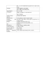
FM:

  1.0 

μ

V for 20 dB (S+N)/N at greater than 1/2 watt of audio 

output 

Selectivity AM/FM:6dB@3KHz,50dB 

@9KHz 


SSB: 6 [email protected],60dB @3.3KHz 

Image Rejection 

More than 65dB 

IF Frequency 

AM/FM: 10.695 MHz 1st IF, 455 KHz 2nd IF     

SSB: 10.695 MHz 

Adjacent-Channel 
Rejection 

60dB AM/FM &70 dB SSB 

RF Gain Control 

45 dB adjustable for optimum signal reception 

Automatic Gain 
Control(AGC) 

Less than 10 dB change in audio output for inputs from 10 to 
100,000 microvolt. 

Squelch 

Adjustable; threshold less than 0.5 

μ

V. 

Automatic Squelch Control(only AM/FM) 0.5 

μ

ANL Switchable 
Noise Blanker 

RF type, effective on AM/FM and SSB 

Audio Output Power 

4 watts into 8 ohms 

Frequency Response 

300 to 2800 Hz 

Built-in Speaker 

8 ohms, round. 

External Speaker(Not 
Supplied) 

8 ohms; disables internal speaker when connected. 


Summary of Contents for CS-1000DX

Page 1: ...COMTEX CS 1000DX USER MANUAL Downloaded From www cbradio nl...

Page 2: ...SETUP OPERATING PROCEDURE TO RECEIVE OPERATING PROCEDURE TO TRANSMIT SPECIFICATION WARNIGN To use the radio please connect the antenna to the location B on the back panel of the equipment firstly and...

Page 3: ...resume normal settings The CB Radio will resume factory default once this function is activated How to Operate Step 1 Power off the radio Step 2 Press and hold FUNC and SCAN keys at the same time then...

Page 4: ...etting from a simple and practical point of view b Your CB radio should not interfere with the driver or the passengers c Remember to provide for the passing and protection of different wires e g powe...

Page 5: ...d remember that the microphone cord must stretch to the driver without interfering with the controls of the vehicle 2 ANTENNA INSTALLATION a Choosing your antenna For CB radios the longer the antenna...

Page 6: ...t to pinch or flatten the coaxial cable as this runs the risk of break down and or short circuiting Connect the antenna to location B c Fixed antenna A fixed antenna should be installed in a space as...

Page 7: ...e use the same or a superior type of cable c It is necessary to connect your CB to a permanent and We advise you to connect the power cable directly to the battery as the connection of the CB cable to...

Page 8: ...cm cable b To adjust the SWR meter Set the CB to channel 20 D band in FM put the switch on the SWR meter to position CAL or FWD Press the Push To Talk switch on the microphone to transmit Bring the in...

Page 9: ...ed enabled NB ANL Appears when NB ANL function is started enabled BP Appears when BP function is started enabled ECHO Appears when ECHO function is started enabled VOIC Appears when VOIC function is s...

Page 10: ...se in the absence of an incoming signal For maximum receiver sensitivity it is desired that the control be adjusted only to the point where the receiver background noise or ambient background noise is...

Page 11: ...with the one of your correspondent The mode selector changes the mode of operation of both transmitter and receiver simultaneously Frequency Modulation FM for nearby communications on a flat open fiel...

Page 12: ...he button FUNC Keypad name is to be used in the following operating instruction 16 ROGER BEEP OR BEEP FUNCTION RB Press RB key to enable RGOER BEEP function with RB icon appearing on LCD display Press...

Page 13: ...to be monitored Finally press the DW key again and the two monitoring channels will be alternately indicated on the LCD Radio will automatically start monitoring scanning the two channels When a signa...

Page 14: ...cted the radio would still start scanning when it is time to resume scanning whether there is signal or not in current channel FUNC SCAN SC LIST Scan ADD or Delete Press FUNC SCAN to delete current ch...

Page 15: ...the radio would emit voice prompt and stop transmitting and back to receiving state automatically This function aims to protect the radio against power tube damage from superheating caused by long tra...

Page 16: ...h a type PL 259 plug to be connected 26 CW KEY This jack is for Morse code operation To operate connect a CW key to this jack and place the MODE switch in the CW position LCD display icon CW PRESS TO...

Page 17: ...gnal or not the radio would detect current channel to check whether current channel has weak signal Release AQ key to exit this function Pressing PTT and AQ key at the same time the radio would emit a...

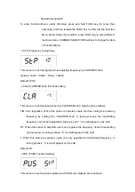
Page 18: ...is to set functions turned by CLARIFIER knob Options are as follows FIN Fine regulation When this option is selected users can fine tuning the receiving frequency by rotating the CLARIFIER knob In tun...

Page 19: ...the transmitting frequency only STP When this option is selected PUSH function will change Frequency Tuning Step of CLARIFIER knob Press this key then the corresponding frequency bit would blink Defau...

Page 20: ...SWR of antenna Once the SWR is beyond the SWR set in advance the radio would prohibit transmitting automatically and loudspeaker will emit voice prompt Then HI S icon will display on the LCD to remind...

Page 21: ...n transmitting SR When SR is selected LCD would display SWR value of antenna when transmitting for example 1 2 on the LCD BAT When BAT is selected LCD would display Supplied Voltage when transmitting...

Page 22: ...Turn the radio on by tuning VOLUME control clockwise 3 Rotate the VOLUME knob to set a comfortable listening level 4 SET the MODE switch to the desired mode 5 Set the CHANNEL selector switch to selec...

Page 23: ...N ASQ switch and coiled cord Input Voltage DC 13 8V normal 15 9V max 11 7V min Transmit AM full mod 5A Receiver Squelched 0 6A SSB 21W PEP output 6A Size 28 25 6CM Weight 1 85kg Antenna Connector UHF...

Page 24: ...rol 45 dB adjustable for optimum signal reception Automatic Gain Control AGC Less than 10 dB change in audio output for inputs from 10 to 100 000 microvolt Squelch Adjustable threshold less than 0 5 V...

Reviews: