background image

Page 4

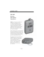
Low Battery Indicator

The LED on the top of the transmitter
indicates the status of the battery as
well as indicating that the unit is turned
on.  When the transmitter is turned on,
the LED illuminates. If the battery is low,
the green LED will blink rapidly to warn
you that the battery will soon be dead.
Replace a low battery immediately.

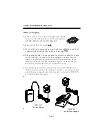
M-169 BATTERY REMOVAL / REPLACEMENT

Pull back battery door latch and allow battery

cover door to spring open.  To remove battery,

simply manipulate the bottom of battery out of

the compartment and remove.

To insert battery, face battery
with negative terminal in line with
large hole in battery compartment,
press battery into compartment and close
battery door until it snaps shut.  Note: It is not
possible to put battery in backwards.

Battery indicator LED

Battery Removal / Replacement

Summary of Contents for M-169

Page 1: ...M 169 OPERATOR S MANUAL PRELIMINARY 357 West 2700 South Salt Lake City Utah 84115 Phone 800 496 3463 Fax 801 484 6906 http www comtek com M 169 Wireless Microphone Transmitter...

Page 2: ...LE OF CONTENTS Introduction Setup Controls Battery Removal Replacement Battery Charging Auxiliary Audio Input Operation Snap On Belt Clip Frequency Selection Frequency Information Optional Accessories...

Page 3: ...in a noisy environment The M 169 incorporates the latest digital and analog technologies to produce low residual noise wide dynamic range and extended frequency response rendering the most natural sou...

Page 4: ...transmitter by inserting the microphone plug into the receptacle on the top of the transmitter The transmitter is operating when the transmitter power switch is turned on and the battery status on in...

Page 5: ...IC ANTENNA JACK This jack accepts an electret type microphone having a 48 long cord with a micro mini 2 5mm mono plug The microphone cord functions as part of the transmitter s antenna system and must...

Page 6: ...Replace a low battery immediately M 169 BATTERY REMOVAL REPLACEMENT Pull back battery door latch and allow battery cover door to spring open To remove battery simply manipulate the bottom of battery o...

Page 7: ...w the battery to charge for 14 hours for a full charge Unit must then be unplugged When using the NBC 9 3 1 digital fast charger the charger will automatically end the charge cycle and the red LED wil...

Page 8: ...ug 1 4 audio phone plug and XLR connectors are available from COMTEK Setup a Connect the microphone to the transmitter by inserting the microphone plug into the receptacle on the top of the transmitte...

Page 9: ...ut with the microphone plugged into the transmitter priority should be given to the microphone gain adjustment The mixing balance between the auxiliary audio and the microphone should be made with the...

Page 10: ...hannel number 1 8 Refer to frequency chart on page 9 Multiple Channel Operation When multiple transmitters are broadcasting in the same immediate area within 100 feet the RF signals will mix together...

Page 11: ...areas should have a 100 ft minimumseparation Operating Area Transmitter Separation 169 MHz BAND CHANNELS CHANNEL FREQUENCY 1 4 6 7 169 445MHz 170 305MHz 171 105MHz 171 845MHz GROUP A CHANNEL FREQUENC...

Page 12: ...p on belt clip supplied with M 175 6 P1 Universal pouch 7 SM 185 Unidirectional electret condenser microphone 8 PSC HM Headworn unidirectional electret microphone Auxiliary Audio Input Cords 9 CB 36 S...

Page 13: ...ction attack time less than 1 ms recovery time 10 ms Frequency Modulation 10kHzdeviation Operating Radio Frequency ity 8 synthesized channels in the 169 445 171 905 MHz band Out of Band Emissions Bett...

Page 14: ...of use of any equipment sold by it COMTEK SPECIFICALLY DISCLAIMS AND NEGATES ANY WARRANTY OF MERCHANTABILITY OR FITNESS FOR A PARTICULAR PURPOSE OF SUCH EQUIPMENT INCLUDING WITHOUT LIMITATION ANY WARR...

Reviews: