QAM Marker
Signal Source
rev1.0.5 August 15, 2017
6
Components
Front Panel
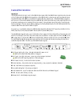
The QAM Marker front panel has two indicators, a reset switch, and a marker selector.
Front Panel
1 Power - Indicates the unit is receiving power.
2 Alarm - Indicates a marker output fault condition. When the Alarm condition is on, the marker
output is shut off.
3 VHF/UHF – Indicates if marker is in the Low Frequency (VHF) or High Frequency (UHF) band
4 Reset - Press to reset a fault condition when the Alarm indicator is on.
5 Marker Identifier - The standard marker setting is 1 for monitoring QAM Marker leakage signals. Using
the selector, the marker can be set to 1, 2, or 3. The QAM Sniffer receiver marker setting must
correspond to the Marker Identifier setting on the headend QAM Marker signal source (F1 for 1, F2
for 2, F3 for 3).
Back Panel
The QAM Marker back panel provides for power, control, and signal connections.
Back Panel
AC Power with built-in fuse - Accepts standard IEC power cord.
DC Power - Dual 48 volt power, screw connection adapter included.
DC Power Fuse (2) - Protection for 48 volt power.
Alarm Remote - Connects to internal relay contacts, screw connection adapter included.
LAN - RJ45 Ethernet network connector.
Ground Binding Post - Chassis ground point.
Combined RF IN - Input for adjacent reference QAM channels combined with QAM Marker.
USB - Service port, factory use only.
+ A - + B -
48 VOLTS DC
1 2
4
3
5


