background image

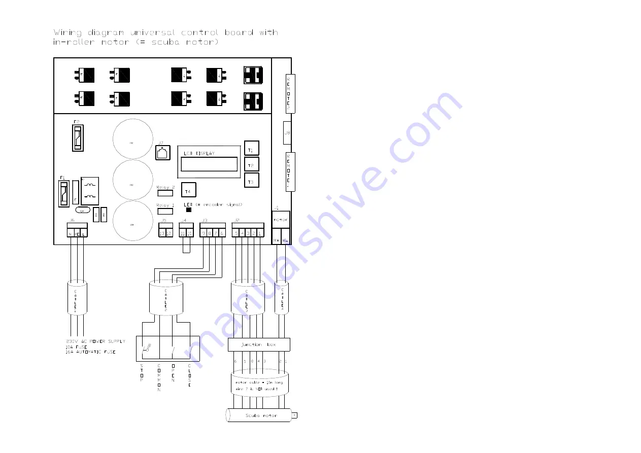
VII.3 : Wiring diagram

Attention:

Use shielded cable with
flexible wires

Motor cable = 10m long

Use the connection box to 
extend the cable

Test the motor before filling
up the connection box with
resin

The resin makes the 
connection waterproof

(Replace the bridge 
between 10-11 by the water 
level contact)

Summary of Contents for Rollo Cover

Page 1: ...CompassPools Rollo Cover Installation Manual ...

Page 2: ...structions II Installation of the Mechanism III Installation of the panel IV Installation of the SS Frame V Installation of the Aluminium Beam VI Installation of the Slats VII Electrical Installation VIII Use and Maintenance IX Warranty ...

Page 3: ...or the electrical installation instructions An overflow and refilling system to maintain a correct water level is highly recommended Do not place any obstacles in the sidewalls of the pool which can interfere with the cover E g skimmers ladders etc Correct tools for the mechanical and electrical installation are inevitable You need 2 persons to install the CompassPools Rollo Cover ...

Page 4: ...er Use enough cement to fill up around the pool in order to have a strong matrix to support it Before filling up the last 50cm around the pool with a sand concrete combination you have to fill up the pool with water till about 20cm This will prevent a narrowing of the pool at water level Roller cover can get blocked Reduced safety as the cover does not rest on the safety edge ...

Page 5: ... shaft fixation parts before the space around the pool is filled up with a sand concrete combination On the following pages you find an exploded view of the different parts together with a detailed part list II 1 To install the mechanism follow the installation sequence II 2 ...

Page 6: ...II 1 Exploded view of the different parts of the mechanism ...

Page 7: ...70mm 12 AT 002009 Wall duct flange 11 AT 002034 Strap to connect the slats to the roller shaft 10 AT 002010 Motor flange 9 AT 002017 Drive block for tube Ø 139 7x2 mm 8 AT 002018 POM bearing for tube Ø 139 7x2 mm drive side 7 AT 002581 In roller motor 24Vdc 6 AT 002066 Seal in PUR 5 AT 002054 Non motor flange 4 AT 002052 Ring to lock secure the roller shaft 3 AT 002019 POM bearing for tube Ø 139 7...

Page 8: ...hanism motor side Use the motor flange as a template The center of the roller shaft will be marked at the Compass factory Mark the 4 bolt holes Mark the centre hole for the motor cable Drill the 4 bolt holes Ø 9mm Drill the center hole Ø 35mm 9 Ø 35mm ...

Page 9: ...side of the pool with bolts M8x35 Put a seal between flange and pool wall Screw the bolts M8x35 into the wall duct flange Put a seal between flange and pool wall II 2 Installation sequence Installation of the mechanism motor side 5 11 9 ...

Page 10: ... mechanism motor side Use silicone to seal off the wall duct flange Use teflon tape to seal the thread Screw the threaded side of the PVC socket on the wall duct flange In the non threaded side of the PVC socket you glue a Ø 32mm rigid PVC tube 15 ...

Page 11: ...llation of the mechanism non motor side Use the motor flange as a template The center of the roller shaft will be marked at the Compass factory Mark the 4 bolt holes Drill the 4 bolt holes Ø 9mm DO NOT drill a center hole on this side ...

Page 12: ...llation of the mechanism non motor side Install the non motor flange inside the pool with bolts M8x30 Put a seal between flange and pool wall These bolts are screwed into the counter flange Put a seal between flange and pool wall 4 16 ...

Page 13: ...II 2 Installation sequence Installation of the mechanism non motor side Install the necessary parts inside the pool Seal off the counter flange with silicone 12 3 16 ...

Page 14: ... 2 Installation sequence Installation of the mechanism roller shaft Make sure you do NOT damage the motor cable while installing the roller shaft Weight of roller shaft including the in roller motor 50kg ...

Page 15: ...llation of the mechanism roller shaft Put enough vaseline in the plastic bearing at the non motor side of the roller shaft Put the non motor side of the roller shaft with the plastic bearing over the stainless steel shaft Ø 30mm 2 12 ...

Page 16: ...sequence Installation of the mechanism roller shaft Place the motor side of the roller shaft in the motor flange Again take care that you do NOT damage the motor cable Lock the motor with 1 bolt M8x90 2 washers and 1 nut ...

Page 17: ...nstallation sequence Installation of the mechanism roller shaft Lock the stainless steel ring at the non drive side onto the Ø 30mm shaft with 2 bolts M8x10 Lock the Ø 30mm shaft with a bolt M10x60 and nut 3 ...

Page 18: ...II 2 Installation sequence Installation of the mechanism roller shaft Attach the straps to the roller shaft so the slats can easily be installed as soon as the pool is filled with water 1 10 ...

Page 19: ...u have to install the panel before the space around the pool is filled up with a sand concrete combination To install the panel follow the installation sequence III 1 Compass Pools delivers you the correct panel together with the pool ...

Page 20: ...III 1 Installation sequence Bring the panel into position The top of the panel has to be at the same level as the safety edge ...

Page 21: ...III 1 Installation sequence Drill 3 holes Ø10mm through pool and panel on the left and right hand side ...

Page 22: ...III 1 Installation sequence Smooth the pool wall Inject enough silicone type INNOTEC ...

Page 23: ...III 1 Installation sequence Use M10x60 SS bolts V4A AISI 316 together with the right washers and nuts to fix the panel properly ...

Page 24: ... made out of SS AISI 304L comes with 1 drain The frame made out of SS AISI 316L comes with 2 drains The SS frame has been treated after welding to have an optimal resistance against corrosion Do not damage or scratch the frame during the installation The stainless steel frame has to be earthed to have an optimal resistance against corrosion Rearth connection 30 Ohm The earth connection is provided...

Page 25: ...hind the cover pit you have to make a strong matrix of a sand concrete combination to support the stainless steel frame Put the matrix over the complete width of the pool LxDxW 400x100x50 cm Pool with cover pit Sand concrete combination ...

Page 26: ...IV 1 Technical drawing of the SS frame Earth connection Regulating bracket ...

Page 27: ... 2 Installation sequence Connect the 90 PVC elbow to the main drain of the skimmer Use the side of the elbow with the internal thread In the other side of the elbow a rigid PVC tube of 50 mm must be glued ...

Page 28: ...IV 2 Installation sequence Cut the rigid PVC tube at 6cm away from the last bracket Use glue to connect the coupling to the rigid PVC tube ...

Page 29: ...IV 2 Installation sequence Use the PVC coupling with a double 50mm glue connection This coupling makes it possible to take the SS frame out of the pool in case of a repair ...

Page 30: ... 2 Installation sequence Install the 5 regulating brackets to the SS frame These brackets make it possible to level the SS frame after installation Do NOT forget to place the extra nut M10 on each bracket ...

Page 31: ...uence Turn the bracket till the end before putting the frame inside the pool Glue some armed PVC liner of 1 2 1 5 mm thick onto the bracket This PVC liner between bracket and pool wall will avoid scratches on the pool wall ...

Page 32: ...IV 2 Installation sequence Put the SS frame in the pool Be careful not to damage the pool Weight of the SS frame 65kg ...

Page 33: ...IV 2 Installation sequence Use 3 cramps to bring the frame in the correct position Use 1 cramp in the middle together with 1 cramp on each side of the frame ...

Page 34: ...V 2 Installation sequence When the frame is in the right position you can start to fix it with stainless steel screws Pre drill the holes in the pool Ø 2mm before fixing them with stainless steel screws ...

Page 35: ...he main drain Use 1 piece of flexible PVC tube Ø 50mm with a length of 30cm Use 1 piece of rigid PVC tube Ø 50mm with a length of 6cm Use 2 90 PVC elbows in which the tubes can be glued Look at the drawing for the right way to put the different parts together ...

Page 36: ...allation sequence Connection of the skimmer to the main drain Connect the prepared part to the coupling you have fixed before Mark the spot on the pool wall where the hole needs to be drilled Drill a hole Ø 60mm ...

Page 37: ...IV 2 Installation sequence Connection of the skimmer to the main drain Smooth and clean the surface around the hole so the wall duct can be installed properly ...

Page 38: ...IV 2 Installation sequence Connection of the skimmer to the main drain Use the wall duct to make a watertight connection ...

Page 39: ...IV 2 Installation sequence Connection of the skimmer to the main drain Use enough silicone as an extra seal around the wall duct Place the white plastic ring before fixing the grey plastic nut ...

Page 40: ...IV 2 Installation sequence Connection of the skimmer to the main drain Lock the plastic nut with a an adjustable spanner ...

Page 41: ...IV 2 Installation sequence Connection of the skimmer to the main drain Use silicone again as an extra seal around the plastic nut ...

Page 42: ...ation sequence Connection of the skimmer to the main drain At the inside of the pool you glue the PVC tube into the wall duct The coupling makes it possible to take the SS frame out of the pool in case of a repair ...

Page 43: ...V 2 Installation sequence Connection of the skimmer to the main drain At the outside of the pool you glue a PVC tube Ø 50mm into the wall duct Lock the plastic nut with the white seal as an extra safety ...

Page 44: ...ng the area around the pool with a sand concrete combination make sure you earth the the frame as an extra protection against corrosion Rearth connection 30 Ohm There is a mounting hole on the frame to install a water level controller Earth connection Mounting hole for water level controller ...

Page 45: ... SS frame you put wooden panels grates to close the cover pit The wooden panels can easily be removed to clean the pit or to do service Make sure the corner coping stones are glued to the frame with silicone so they can be removed in case the frame has to be taken out of the pool Corner coping stones ...

Page 46: ...protection against corrosion Be careful not to damage or scratch the beam during the installation The aluminium beam has a SS bracket on each side to adjust its level In the back wall behind the roller cover you install a skimmer with water level controller The cover pit can be covered with wooden or polypropylene grates Chapter V 1 Installation sequence Only valid with COMFORT LINE Only valid wit...

Page 47: ...aluminium beam has an adjustable bracket on each side to regulate the level Make sure you have minimum 30mm between waterlevel and panel AND between water level and beam If not slats might get stuck Put the bracket on the pool wall ...

Page 48: ...w of the aluminium beam with the adjustable bracket Optional you can fix the bracket on top of the pool to prevent it from moving Use SS screws and plugs or bolts to fix the beam Detail of the aluminium beam with support for the grates ...

Page 49: ... the cover pit with polypropylene PP grates On 1 side the grates rest on the pool wall on the other side the grates rest on the aluminium beam Dimenions of the PP grates 750 925 x 500 mm If necessary the grates can be cut to size on site PP ...

Page 50: ...V 1 Installation sequence Another option is to install grates out of tropical wood Dimenions of the wooden grates 750 925 x 600 mm If necessary the grates can be cut to size on site WOOD ...

Page 51: ...m the sunlight Respect the sequence of the slats in the crate the slats for the pool end are on top those connecting to the shaft are at the bottom Orientation of the slats the curved side is the top side open side towards pool end Roll up the slats while carrying them to the pool They come in a carboard box with different layers Each layer has 9 slats With solar slats the filtration pump must alw...

Page 52: ... the slats will slowly come together Use the straps to connect the slats to the roller shaft Threaded holes with bolts and washers are provided in the shaft Different holes are provided in the straps so they can be cut to size Do not fix the slats directly to the roller shaft ...

Page 53: ...ectrical preparations VII 2 Overview of the different parts VII 3 Wiring diagram VII 4 Technical chart VII 5 Initializing of the control box VII 6 Remote control VII 7 Extended manual VII 8 Problem solving with overview of the error codes ...

Page 54: ...VII 1 Electrical preparations VII 1 Electrical preparations Motor cable is always 10m long ...

Page 55: ...ol board This box has to be installed in the plant room never outdoor Use flexible wires for all connections Key switch This box has to be placed there where you can see the pool Put the key on 0 as an emergency stop or to reset an error message ...

Page 56: ...I 2 Overview of the different parts In roller motor with 10m chlorine resistant cable Use flexible wire to extend this cable Use the connection box with the polyester resin to make a watertight connection ...

Page 57: ...e with flexible wires Motor cable 10m long Use the connection box to extend the cable Test the motor before filling up the connection box with resin The resin makes the connection waterproof Replace the bridge between 10 11 by the water level contact ...

Page 58: ...gnal 5 Sensor 4 Sensor 3 Brake 2 Brake 1 J2 Motor or M2 Motor or M1 J1 Connector relay card 2 Relay2 Connector relay card 1 Relay1 Connection receiver print remote control Remote 1 Use flexible wires Min 2 x 4 mm CABLE4 Use flexible wires Min 5 x 0 75 mm shielded CABLE3 Use flexible wires Min 4 x 0 75 mm CABLE2 Use flexible wires Min 3 x 1 5 mm CABLE1 Description Code ...

Page 59: ...your choice enter T2 Scroll up OPEN T1 Fuse 20A F2 Glass fuse 2A F1 Extra connector for remote control signal J8 Ethernet connection J7 Power supply 230V N Earth PE Power supply 230V L J6 Optional Programmable input 13 Optional Programmable input 12 J5 ...

Page 60: ...ng the control box Follow the next steps Use pushbuttons T1 and T3 to scroll up and down To confirm your choice use pushbutton T2 enter To enter the Menu use pushbutton T4 Use T4 also to return to the previous step STEP1 Display A Enter the menu STEP2 Display B Select language Push T4 MENU Select your language and confirm with T2 ...

Page 61: ... and confirm with T2 STEP5 Display E Program end positions Push T1 and hold the button to open the cover to the end position To save the OPEN position first push T2 hold and simultaneously push T1 Confirmation will appear on the LCD screen Push T3 and hold the button to close the cover to the end position To save the CLOSE position first push T2 hold and simultaneously push T3 Confirmation will ap...

Page 62: ...STEP6 Display F Cover is ready for use The cover is now ready for use you can use the control buttons on the key switch to operate the cover ...

Page 63: ...y card with the plastic plugs and connect the card to Relay 1 on the control board Step 4 Switch your pool lights with relay 4 ATTENTION the relays can have maximum 16A Step 5 Test your remote control using the transmitter If necessary install the antenna Channel A is used to control the roller cover Channel B is used to switch the pool lights Wiring diagram for the pool lights ...

Page 64: ...7 MEMO button 6 Connector to plug the receiver on the control board 5 Plastic plugs to connect the relay card to the control box housing 4 Relay 4 Use this relay to switch the pool lights 3 Data cable to connect the relay card to the control board 2 Relay card with 4x 16A relays 1 Part description Nr Receiver Transmitter 5 6 7 8 9 10 11 core mantle ...

Page 65: ...the menu to reprogram the end positions or to set further options Use pushbuttons T1 and T3 to scroll up and down To confirm your choice use pushbutton T2 enter To enter the Menu use pushbutton T4 Use T4 also to return to the previous step Enter the menu Setting 1 Language settings Push T4 MENU Select your language and confirm with T2 Use T4 to return to the menu ...

Page 66: ...ection of rotation is correct confirm with T2 ATTENTION When you change the direction of rotation you are obliged to reprogram the end positions Setting 4 Program end positions Push T1 and hold the button to open the cover to the end position To save the OPEN position first push T2 hold and simultaneously push T1 Confirmation will appear on the LCD screen Push T3 and hold the button to close the c...

Page 67: ...ND YOU STILL HAVE THE SAME ERROR CONTACT YOUR DEALER THE MAXIMUM CURRENT OF THE MOTOR HAS BEEN REACHED MAXIMUM CURRENT CHECK WATER LEVEL OF THE POOL AND RESET THE ERROR WITH THE KEY AS SOON AS IT IS CORRECT NO CONNECTION BETWEEN 10 11 ON THE CONTROL BOARD WATER LEVEL NOT CORRECT OR NO BRIDGE BETWEEN 10 11 WATER LEVEL 1 TURN THE KEY ON THE KEYSWITCH TO 1 NO CONNECTION BETWEEN 8 9 ON THE CONTROL BOA...

Page 68: ...ay from the pool while the cover is in operation Check if the water level of the pool is correct or equip the pool with an automatic level control and overflow Keep an eye on the movement of the pool cover during the opening and closing In case of irregularities stop the pool cover immediately by turning the key switch to 0 It is not allowed to manually open and close the cover ...

Page 69: ...water the slats must be protected against direct sunlight Therefore check the water level regularly At extremely low temperatures frost the slats become more fragile The pool cover may not be trod on or come into contact with hard objects During a hail storm the pool cover must be opened in order to prevent damage The filtering installation must always be operational when the cover is closed Just ...

Page 70: ...rost free normal operation of the cover Pool not in operation filtration stopped and lower water level Clean the slats and roll them onto the roller shaft Protect the slats from sunlight Failure In case of a failure contact your dealer ...

Page 71: ...red to replace or provide compensation for the articles or components to which the complaint relates The complaint should be submitted to us in writing within 7 days of the development of the problem Consequential damage and the costs of assembly dismantling and transport are not covered by the guarantee The manufacturer s responsibility ceases to apply if the defect arises as a result of injudici...

Reviews: