


United States January 2, 2003
Presario 1600 Series
Models: 1600T, 1600-XL140, 1600-XL141, 1600-XL142, 1600-XL143,
1600-XL144, 1600-XL145, 1600-XL146, 1600-XL147, and 1600-XL150
Before You Begin
Product Description
Parts Catalog
Specifications
Battery Operations
Pin Assignments
Removal Sequence
Troubleshooting
MSG Index
Preliminary
Steps
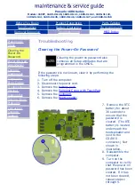
Clearing the
Power-On
Password
Power-On Self
Test (POST)
Compaq
Diagnostics
Diagnostic
Error Codes
Troubleshooting
Without
Diagnostics
Solving Minor
Problems
Contacting
Compaq
Support
Troubleshooting
Diagnostic Error Codes
Diagnostic error codes occur if the system recognizes a problem
while running the Compaq Diagnostic program. These error codes
help identify possibly defective subassemblies.
The following tables list error codes, a description of the error
condition, and the action required to resolve the error condition.
IMPORTANT:
Retest the system after completing
each step. If the problem has been
resolved, do not proceed with the
remaining steps.
For the removal and replacement of a particular subassembly, see
Removal and Replacement Procedures
.
Select error codes by number or type:
101 through 114
Processor Test
200 through 215
Memory Test
300 through 304
Keyboard Test
401 through 403
Parallel Printer Test
501 through 516
Video Test
1101
Serial Test
1701 through 1736
Hard Drive Test
2402 through 2456
Video Test
2419 through 2456
Video Test
2458 through 2480
Video Test
3206
Audio Test
3301 through 6623
DVD or CD Test
8601 through 8602
TouchPad Pointing Device
Test
Processor Test Error Codes
Error
Code
Description
Recommended Action
101-xx CPU test failed
Replace the processor and
retest.
102-xx Coprocessor or Weitek
Error
1. Run the Configuration and
Diagnostics Utilities.
2. Replace the processor
board and retest.
103-xx DMA page registers test
failed
Replace the system board
and retest.
104-xx Interrupt controller
master test failed
105-xx Port 61 error
106-xx Keyboard controller self-
test failed
107-xx CMOS RAM test failed
108-xx CMOS interrupt test failed
109-xx CMOS clock test failed
110-xx Programmable timer load
data test failed
113-xx Protected mode test
failed
114-01 Speaker test failed
1. Check system
configuration.
2. Verify cable connections
to speaker.
3. Replace the system board
and retest.
Top of Page
Memory Test Error Codes
Error
Code
Description
Recommended Action
200-xx Memory machine ID test
failed
1. Flash the system ROM
and retest.
2. Replace the system board
and retest.
202-xx Memory system ROM
checksum failed
203-xx Write/Read test failed
1. Remove the memory
module and retest.
2. Install a new memory
module and retest.
204-xx Address test failed
211-xx Random pattern test
failed
214-xx Noise test failed
215-xx Random address test
failed
Top of Page
Keyboard Test Error Codes
Error
Code
Description
Recommended Action
300-xx Failed ID Test
1. Check the keyboard
connection. If
disconnected, turn off the
computer and connect the
keyboard.
2. Replace the keyboard and
retest.
3. Replace the system board
and retest.
301-xx Failed Self-test/Interface
Test
302-xx Failed Individual Key Test
304-xx Failed Keyboard Repeat
Test
Top of Page
Parallel Printer Test Error Codes
Error
Code
Description
Recommended Action
401-xx Printer failed or not
connected
1. Connect the printer.
2. Check power to the
printer.
3. Install the loop-back
connector and retest.
4. Check port and IRQ
configuration.
5. Replace the system board
and retest.
402-xx Failed Port Test
403-xx Printer pattern test failed
Top of Table
Diskette Drive Test
Error
Code
Description
Recommended Action
600-xx
Diskette ID drive types
test
failed
1. Replace the diskette
media and retest.
2. Check and/or replace the
diskette power and signal
cables and retest.
3. Replace the diskette drive
and retest.
4. Replace the system board
and retest.
601-xx Diskette format failed
602-xx Diskette read test failed
603-xx Diskette write, read,
compare test failed
604-xx Diskette random read
test failed
605-xx Diskette ID media failed
606-xx Diskette speed test failed
609-xx Diskette reset controller
test failed
610-xx Diskette change line test
failed
697-xx Diskette type error
698-xx Diskette drive speed not
within limits
699-xx
Diskette drive/media ID
error
1. Replace media.
2. Run the Configuration and
Diagnostics Utilities.
Top of Page
Serial Test Error Codes
Error
Code
Description
Recommended Action
1101-
xx
Serial port test failed
1. Check port configuration
2. Replace the system board
and retest.
Top of Page
Hard Drive Test Error Codes
Error
Code
Description
Recommended Action
1701-
xx
Hard drive format test
failed
1. Run the Configuration
and Diagnostics Utilities
and verify drive type.
2. Verify that all secondary
drives have secondary
drive capability.
3. Replace the hard drive
and retest.
4. Replace the system
board and retest.
1702-
xx
Hard drive read test failed
1703-
xx
Hard drive
write/read/compare test
failed
1704-
xx
Hard drive random seek
test failed
1705-
xx
Hard drive controller test
failed
1706-
xx
Hard drive ready test
failed
1707-
xx
Hard drive re-calibration
test failed
1708-
xx
Hard drive format bad
track test failed
1709-
xx
Hard drive reset controller
test failed
1710-
xx
Hard drive park head test
failed
1715-
xx
Hard drive head select
test failed
1716-
xx
Hard drive conditional
format test failed
1717-
xx
Hard drive ECC* test
failed
1719-
xx
Hard drive power mode
test failed
1724-
xx
Network preparation test
failed
1736-
xx
Drive monitoring test
failed
* ECC = Error Correction Code
Top of Page
Video Test Error Codes
Error
Code
Description
Recommended Action
501-xx Video controller test
failed
The following steps apply to
error codes 501-xx through
516-xx:
1. Disconnect external
monitor and test with
internal LCD display.
2. Replace the display
assembly and retest.
3. Replace the system board
and retest.
502-xx Video memory test failed
503-xx Video attribute test failed
504-xx Video character set test
failed
505-xx
Video 80 x 25 mode 9 x
14 character cell test
failed
506-xx Video 80 x 25 mode 8 x 8
character cell test failed
507-xx Video 40 x 25 mode test
failed
508-xx Video 320 x 200 mode
color set 0 test failed
509-xx Video 320 x 200 mode
color set 1 test failed
510-xx Video 640 x 200 mode
test failed
511-xx Video screen memory
page test failed
512-xx Video gray scale test
failed
514-xx Video white screen test
failed
516-xx Video noise pattern test
failed
Video Test Error Codes Continued
Error
Code
Description
Recommended Action
2402-
xx
Video memory test failed The following steps apply to
error codes 2402-xx through
2456-xx:
1. Run the Configuration and
Diagnostics Utilities.
2. Replace the display
assembly and retest.
3. Replace the system board
and retest.
2403-
xx
Video attribute test failed
2404-
xx
Video character set test
failed
2405-
xx
Video 80 x 25 mode 9 x
14 character cell test
failed
2406-
xx
Video 80 x 25 mode 8 x 8
character cell test failed
2408-
xx
Video 320 x 200 mode
color set 0 test failed
2409-
xx
Video 320 x 200 mode
color set 1 test failed
2410-
xx
Video 640 x 200 mode
test failed
2411-
xx
Video screen memory
page test failed
2412-
xx
Video gray scale test
failed
2414-
xx
Video white screen test
failed
2416-
xx
Video noise pattern test
failed
2418-
xx
ECG/VGC memory test
failed
Video Test Error Codes Continued
Error
Code
Description
Recommended Action
2419-
xx
ECG/VGC ROM checksum
test failed
1. Run the Configuration and
Diagnostics Utilities.
2. Disconnect external
monitor and test with
internal LCD display.
3. Replace the display
assembly and retest.
4. Replace the system board
and retest.
2421-
xx
ECG/VGC 640 x 200
graphics mode test failed
2422-
xx
ECG/VGC 640 x 350 16
color set test failed
2423-
xx
ECG/VGC 640 x 350 64
color set test failed
2424-
xx
ECG/VGC monochrome
text mode test failed
2425-
xx
ECG/VGC monochrome
graphics mode test failed
2431-
xx
640 x 480 graphics test
failure
2432-
xx
320 x 200 graphics (256
color mode) test failure
2448-
xx
Advanced VGA Controller
test failed
2451-
xx
132-column Advanced
VGA test failed
2456-
xx
Advanced VGA 256 Color
test failed
Video Test Error Codes Continued
Error
Code
Description
Recommended Action
2458-
xx
Advanced VGA BitBLT
test
The following applies to error
codes 2458-xx through 2480-
xx:
Replace the system board
and retest.
2468-
xx
Advanced VGA DAC test
2477-
xx
Advanced VGA data path
test
2478-
xx
Advanced VGA BitBLT
test
2480-
xx
Advanced VGA LineDraw
test
Top of Page
Audio Test Error Codes
Error
Code
Description
Recommended Action
3206-
xx
Audio System Internal
Error
Replace the system board
and retest.
Top of Page
TouchPad/Pointing Device Interface Test Error Codes
Error
Code
Description
Recommended Action
8601-
xx
Mouse test failed
1. 1. Replace the TouchPad
and retest.
2. Replace the system board
and retest.
8602-
xx
Interface test failed
Top of Page
DVD or CD Drive Test Error Codes
Error
Code
Description
Recommended Action
3301-
xx
DVD or CD drive read
test failed
1. 1. Replace the DVD or CD
and retest.
2. Verify that the speakers
are connected.
3. Verify that drivers are
loaded and properly
installed.
4. Replace the DVD or CD
drive and retest.
5. Replace the system board
and retest.
3305-
xx
DVD or CD drive seek
test failed
6600-
xx
ID test failed
6605-
xx
Read test failed
6608-
xx
Controller test failed
6623-
xx
Random read test failed
Top of Page
privacy and legal statement
All manuals and user guides at all-guides.com