Compact Power BOXER 118 Operator'S Manual Download Page 42

3-14

Pre-Start Inspection and Operation


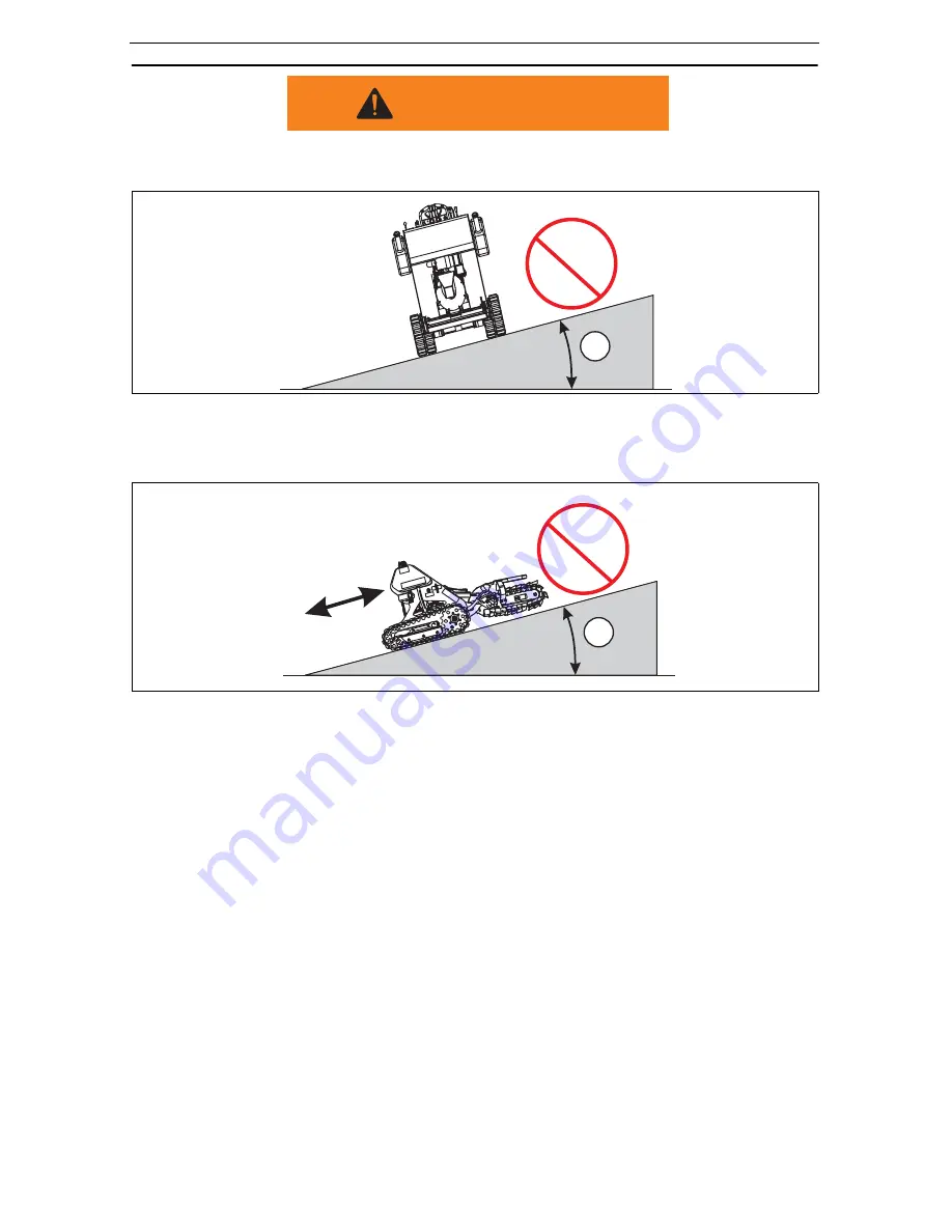
• Do not travel up or across a slope steeper than 15°. See 

Figure 3–15

.

• Keep boom as low as possible when traveling on slopes or rough terrain.

Figure 3–15 Slide Slope Travel

• Keep the heavy end of the machine towards the uphill direction when traveling up 

or down a slope. See 

Figure 3–16

.

Figure 3–16 Uphill/Downhill Travel

WARNING

P

15

°

>15

°

1

6

16

2437

P

15

°

>15

°

2438

Summary of Contents for BOXER 118

Page 1: ...COMPACT COMPACT TM COMPACT COMPACT Part No 999 823 Serial No s 005 and Higher BIG POWER IN ALL PLACES 118 Operator s Manual...

Page 2: ...locate the Serial Number plate Record SERIAL Number here MANUFACTURED BY MANUFACTURED BY MODEL NO S N ENGINE SERIAL NO ENGINE SERIAL NO WEIGHT POWER COMPACT POWER EQUIPMENT 800 476 9673 cpiequipment c...

Page 3: ......

Page 4: ......

Page 5: ...uipment or parts to Mertz Manufacturing LLC or to an authorized dealer facility freight prepaid within fifteen 15 days after the defective condition is discovered All warranties if any extended to Mer...

Page 6: ...val or reinstallation CONSEQUENTIAL DAMAGES Notwithstanding any other provision of this agreement in no event shall Mertz Manufacturing LLC be liable whether arising under contract tort including negl...

Page 7: ...uthorized Distributor Dealer will repair or replace any such track free of charge during that period Prorated discount structure If the original track becomes unserviceable within the first 100 hours...

Page 8: ...a warranty credit in the amount of his cost for the track less 62 If the hours are less that 200 on the original track a labor allowance of hour will also be credited No replacement labor will be pai...

Page 9: ...returning the form could result in your being denied some of your warranty entitlements To have Mertz Manufacturing LLC reset the warranty start date please complete the form below and mail or fax it...

Page 10: ...vi Mertz Manufacturing LLC P O Box 150 Ponca City OK 74602 Affix Stamp Here...

Page 11: ...ns indicated whenever you see the Safety Alert symbol no matter which signal word appears next to the Safety Alert symbol INDICATES A HAZARDOUS SITUATION THAT IF NOT AVOIDED IS VERY LIKELY TO CAUSE DE...

Page 12: ...viii...

Page 13: ...ntrols 2 3 Safety Decals 2 4 Operating Controls Description 2 5 Section 3 Pre Start Inspection and Operation 3 1 Pre Start Inspection 3 1 Daily Service Checks 3 1 Operating Instructions 3 7 Machine St...

Page 14: ...x Configuring the Chain 4 29 Parts List 4 30 Boxer 118 Hydraulic Interconnect Diagram 4 32 Section 5 Troubleshooting 5 1 Section 6 General Specifications 6 1 Noise Data 6 2...

Page 15: ...ldren wander onto the job site Resume work only when the operating area is clear Keep all non operating personnel away from the machine during operation Passengers must never be allowed to ride on the...

Page 16: ...itions you may encounter are Holes Deep ditches or excavations Drop offs Soft un compacted soil Culverts Deep mud Standing Water Large rocks Slippery surfaces Steep slopes Tall grass trees or shrubs I...

Page 17: ...opes can be dangerous and there is a greater risk of the machine tipping over or becoming unstable The list of rules below must be understood and followed for maximum safety Avoid excessively steep sl...

Page 18: ...work site hazards Be sure the area has adequate light and is well ventilated NEVER operate the machine inside a closed area Clean up any oil grease mud water or snow which might cause the floor surfac...

Page 19: ...fire or an explosion If electrolyte is splashed into your eyes flush them immediately with clean water and seek medical attention If electrolyte is swallowed seek medical attention immediately If ele...

Page 20: ...ny hydraulic lines Hot hydraulic fluid can cause severe burns Hydraulic oil under pressure can penetrate body tissue causing serious injury and possible death When troubleshooting a hydraulic system f...

Page 21: ...he machine before beginning the fueling process Keep the fuel nozzle in constant contact with the rim of the machines fuel tank When filling a portable gas container always place it on the ground Neve...

Page 22: ...1 8 Safety Precautions...

Page 23: ...ew Item No Description 1 Operating Controls 2 Hydraulic Fluid Level Dipstick and Tank Fill Port 3 Hydraulic Tank 4 Track Adjusting Wrench 5 Right Hand Track Drive 6 Trencher Drive Motor 7 Trencher Ass...

Page 24: ...rols Left Rear View Item No Description 1 Fuel Gauge and Fuel Filler Cap 2 Gas Tank 3 Rock Guard 4 Spoils Auger 5 Left Track Assembly 6 Operator s Platform 7 Trencher Activation Lock Lever 8 Engine 1...

Page 25: ...n 1 Fuel Gauge and Fuel Filler Cap 2 Left Hand Grip 3 Trencher Boom Raise and Lower Control Lever 4 Left Travel Control Lever 5 Right Travel Control Lever 6 Right Hand Grip 7 Trencher Activation Contr...

Page 26: ...Warning 5 Tie Down and Lifting Hazard Decals 6 Boxer Logo 7 Crush Hazard Decal 8 Stand Clear Warning Decal 9 Entanglement Hazard Decal 10 Shock Hazard Decal 11 Read Manual Decal 12 Fuel Explosion Haz...

Page 27: ...the control lever the operator my step on the operator presence control lever and hold the lever in the downwards position This allows the trencher control lever to be moved a The center and forward...

Page 28: ...rts and stops the engine 10 Trencher Activation Operator Presence Pedal This pedal must be stepped on and held in the downwards position before the trencher control lever is moved from the center Neut...

Page 29: ...ck and refill the fuel tank Check hydraulic lines and hoses for signs of damage or leaks Inspect the machine for any signs of damage or loose fasteners Check fluid levels and any signs of leaking flui...

Page 30: ...nt decals 2 Check engine oil The engine oil dip stick and engine oil filler port can be reached through the top openings of the front protective cover Make sure that the engine is OFF Pull out the dip...

Page 31: ...utes and check the oil level again Make sure to securely reinstall the dipstick into the dipstick tube before starting the engine Allow engine to cool before filling fuel tank Do not overfill the fuel...

Page 32: ...ve been made Some examples of common hydraulic hose damage are shown in Figure 3 3 Figure 3 3 Hydraulic Hose Damage 1 End fittings damaged or leaking 2 Outer covering chafed or cut and wire reinforcin...

Page 33: ...ation 8 Grease pivot shafts with proper type of grease There are 5 grease points on this machine see Figure 3 4 The grease zerk below the chain tension bolt should only be greased monthly Figure 3 4 G...

Page 34: ...or presence control and shift the Trencher Control Lever to the right into the trenching position The control lever should remain in that position as long at the dead man control is held down Releasin...

Page 35: ...starts release the starter key The key will automatically return to the RUN position 6 Leave the throttle setting at about the halfway position and allow the engine to idle This will begin warming the...

Page 36: ...assemblies trencher chain assembly etc Transportation 1 Move the throttle control lever to the mid range engine speed Raise the boom so that it will clear the ramp of the transport trailer It is recom...

Page 37: ...ecommended to secure the machine through the tie downs Item 3 Figure 3 7 located on each side of the machine framework Lifting Procedures When it becomes necessary to lift the machine 1 Start the engi...

Page 38: ...d for working conditions could cause an unsafe situation Make sure to maintain your grip on both of the hand grips any time the machine is in motion Due to the spring tension system built into the tra...

Page 39: ...drive sprocket to seat into the rubber track incorrectly and cause damage to the track If cogging occurs stop travel function and check for and remove any debris or foreign matter in the drive system...

Page 40: ...arther forward the right control is moved the faster the left turn will be made See Figure 3 11 2431 Figure 3 11 Left Hand Turn in Forward Right Turn During Reverse Travel Left Turn During Reverse Tra...

Page 41: ...ve the travel control levers in opposite directions to spin the machine on it axis To spin left move the right control lever forward while pulling the left control lever backwards to spin turn to the...

Page 42: ...ure 3 15 Keep boom as low as possible when traveling on slopes or rough terrain Figure 3 15 Slide Slope Travel Keep the heavy end of the machine towards the uphill direction when traveling up or down...

Page 43: ...tructions in this manual refer to a power unit that has an operator presence control that when released that automatically shuts off the trencher but allows the engine to continue to operate Since Com...

Page 44: ...on Figure 3 17 Trencher Boom in Raised Position 3 Depress step on and hold the operator presence control Item 1 Figure 3 18 in the down or activated position with your right foot Figure 3 18 Trencher...

Page 45: ...ntrol Figure 3 19 Trencher Chain Control Lever in Forward Position 5 Using the boom lower control slowly rotate the trencher boom downwards until it makes contact with the ground See Figure 3 20 Conti...

Page 46: ...unstable Use a travel speed only as fast as ground conditions will permit smooth and even trenching 8 When the travel speed has been set properly for the digging conditions steering and direction con...

Page 47: ...nd move the trencher out of the way When the trenching has been completed move the engine throttle to the idle position and allow the engine to cool off at idle for 3 4 minutes 11 Lower the trencher b...

Page 48: ...3 20 Pre Start Inspection and Operation...

Page 49: ...dusty or dirty working conditions may require more frequent service replacement Under very wet and muddy conditions more frequent lubrication may be required Activity Daily 10 Hours New Machine 20 Ho...

Page 50: ...and understand all WARNING and SAFETY decals before operating the machine 2 Check engine oil The engine oil dip stick and engine oil filler port can be reached through the top openings of the front pr...

Page 51: ...ecurely reinstall the dipstick into the dipstick tube before starting the engine d After filling the oil wait a few minutes and check the oil level again Allow engine to cool before filling fuel tank...

Page 52: ...air part Figure 4 3 Air Filter Assembly Extremely dusty or dirty working conditions may require more frequent service replacement 5 Check all hydraulic hoses lines and fittings Hydraulic oil under pre...

Page 53: ...y 7 While you are performing the daily maintenance inspect the machine for any signs of damage such as missing or damaged components cracked welds etc 8 Check the track assemblies to make sure that a...

Page 54: ...ions 10 Check for proper track tension a Remove the track adjusting wrench Item 2 Figure 4 6 from the right track assembly Make sure that the rubber grommets remain on the threaded studs Item 3 Figure...

Page 55: ...needed remove the adjustment nut lock plate and rotate the tension adjustment nut Item 2 Figure 4 6 until the proper track deflection measurement is achieved Reinstall and secure the adjustment nut lo...

Page 56: ...the operator presence control is held down Releasing the operator presence control returns the Trencher Control Lever to the neutral position If any of the levers other than the Trencher Control Lever...

Page 57: ...used hydraulic fluid in an appropriate manner and according to State and Local regulations Place a container under the upper hydraulic tank to capture any hydraulic fluid that may drain out a Remove...

Page 58: ...sing the hydraulic oil level dip stick Item 1 Figure 4 10 check the hydraulic oil level Add the appropriate hydraulic fluid as needed through the filler port Item 2 Figure 4 10 on top of the upper hyd...

Page 59: ...nce procedures Check the battery Item 3 Figure 4 11 and cable connections Items 1 and 2 Figure 4 11 for signs of leaking corrosion or damage To complete this check remove the service access panel Make...

Page 60: ...access the top of the engine b Remove the air filter cover Item 1 Figure 4 12 and the outer air filter sleeve Item 4 Figure 4 12 c Loosen and remove the wing nut Item 2 Figure 4 12 holding the air fi...

Page 61: ...2 Figure 4 13 along the left side of the engine b Shut off fuel using the fuel shut off valve Item 1 Figure 4 13 by rotating the valve handle horizontally across the fuel line c Remove the spring cla...

Page 62: ...isible remove and replace the battery Wear the proper protective clothing when handling the battery Leaking battery fluid contains acid that can cause burns Fumes from the leaking fluid can cause resp...

Page 63: ...h Reinstall and secure the cable clamps 11 Check the battery hold down clamp Items 4 and 7 Figure 4 14 to make sure that the battery is being held securely to the machine If the battery needs to be re...

Page 64: ...in all hydraulic fluid from the machine Make sure to inspect the O ring Item 2 Figure 4 15 on the drain plug Replace the O ring if any signs of damage are noted Figure 4 15 Hydraulic Tank Drain Plug c...

Page 65: ...ure 4 16 and fill the hydraulic tank with the proper hydraulic fluid Chevron Rykon Premium ISO 46 or equivalent until the fluid level is at but not above the upper marker hole in the dipstick Do not o...

Page 66: ...NKS SHOULD ONLY BE DRAINED IN AN AREA THAT IS WELL VENTILATED 5 WIPE UP ANY GASOLINE THAT SPILLS 1 Park the machine on a level surface to make sure that the fuel tank is completely drained 2 Lower the...

Page 67: ...earlier in this section The old fuel filter will be filled with gasoline Make sure to drain the fuel from the filter into an appropriate container Dispose of the used fuel filter in an appropriate ma...

Page 68: ...the boom and the top of the bottom chain span See Figure 4 18 For a new chain check the chain sag after the first hour of operation Depending on working conditions chain sag adjustments may need to b...

Page 69: ...gure 4 19 2 Rotate the chain adjustment bolt Item 3 Figure 4 19 to increase or decrease pressure on the boom until the proper chain sag is measured 3 Tighten the adjustment bolt lock nut 4 On a monthl...

Page 70: ...Tension Adjustment Bolt lock nut Item 5 Figure 4 20 and Chain Tension Adjustment Bolt Item 4 Figure 4 20 to fully release the chain tension 3 Remove the chain from the boom tip sprocket The trencher...

Page 71: ...4 23 Routine Service and Maintenance 10 Reinstall the boom guard Item 1 Figure 4 20 Figure 4 20 Trencher Boom Assembly 1 2 3 4 5 6 7 2463...

Page 72: ...le tooth Items 3 and 5 Figure 4 20 remove the bolts and nuts Item 1 and 2 Figure 4 21 securing the tooth to remove it and then install a new tooth in the same position The spacer tubes Item 4 Figure 4...

Page 73: ...ove the chain from the boom 5 Remove the chain Item 2 Figure 4 22 from the drive sprocket Item 4 Figure 4 22 by removing the master link pivot pin See Chain Master Link later in this section 6 Remove...

Page 74: ...chain around the roller at the end of the boom Connect the chain together as shown in the Chain Master Link on page 28 for instructions 12 Tighten the chain tension adjustment bolt until the proper ch...

Page 75: ...move soil Triangular rock teeth cut rock and other hard ground The teeth are cupped or angled differently depending on which side of the chain they are intended to be fastened i e either left or right...

Page 76: ...Item 1 Figure 4 24 which will have a remov able pivot pin and cotter pin instead of two bolts 2 Support the trencher chain from underneath the trencher frame 3 Remove the cotter pin Item 2 Figure 4 24...

Page 77: ...each tooth set together so you can assemble them later 3 Install each tooth set across the top span from front to back in the order listed in the appropriate chain configuration table Install the toot...

Page 78: ...LT 3 8 24 X 3 8 382438 4 BOLT 3 8 24 X 2 1 2 12 38242128 6 BOLT 3 8 24 X 3 3 4 8 38243348 8 LOCK NUT 64 3824 9 FLAT WASHER 16 382S 10 SPACER TUBE 1 3 8 52 B135320 11 LEFT TERMINATOR TOOTH 8 T165404L 1...

Page 79: ...rvice and Maintenance Figure 4 25 Chain Configuration 12 10 11 2 9 8 8 12 10 11 6 9 16 8 13 10 14 4 Configuration A 14 10 13 8 17 3 14 15 13 8 1 Configuration B Configuration C Configuration D Configu...

Page 80: ...draulic Interconnect Diagram Figure 4 26 Boxer 118 Hydraulic Interconnect Diagram AUX VALVE FILTER IN TANK RETURN TO TANK VENT TILT CYL TRACK MODULE BACK ROD END CONTROL VALVE TOP MOTOR RIGHT MOTOR LE...

Page 81: ...ay or starter switch is defective Contact Authorized Service Dealer Engine is in hydraulic lock due to a cylinder filled with fuel Allow engine to cool before attempting this procedure Remove spark pl...

Page 82: ...fuel tank with fresh clean fuel Replace fuel filter Engine overheats Engine load is excessive Reduce ground speed Reduce speed of trencher Engine oil level in crankcase is low Add the appropriate eng...

Page 83: ...contain rocks or other items that are preventing smooth operation Raise trencher chain from the trench to clear contact with the obstruction Power unit is low on hydraulic fluid Check and fill the hy...

Page 84: ...5 4 Troubleshooting...

Page 85: ...turning type controls Warranty Engine Warranty Two Year Product Warranty One Year Ground Drive System Dimensions Units English Metric Trench Depth 24 36 in 610 914 mm Trench width 4 8 in 101 203 mm Bo...

Page 86: ...ance with EU Machinery Directive 98 37 EC EN 474 10 2006 in addition to ISO DIS 6394 2004 Engine RPM was 3600 rpm max rpm The noise measurements were made with the operator present The declared value...

Page 87: ...S A 15 DEGR EE SLOP E DO NOT TRAVEL ACROSS OR UP AND DOWN A SLOPE GREATER THAN 15 DEGREES DO NOT TRAVEL ACROSS OR UP AND DOWN A SLOPE GREATER THAN 15 DEGREES To avoid serious injury operate your unit...

Page 88: ...Compact Power Inc P O Box 40 Fort Mill SC 29716 Phone 800 476 9673 Fax 803 548 2762 Web Site http www cpiequipment com Part Number 999 823...

Reviews: