Community VERIS Series - Operation and Installation Manual - Page 36
VERIS 15
VERIS 15 Notes:
The VERIS 15 has a total of 13 x M10 hang points plus 4 x M8 rear mounting points for OmniMount™ 60 Series inserts.
Page 1: ...VERIS Series VERsatile Installation Systems Exquisite Performance Exceptional Value Operation Manual ...
Page 2: ...es and regulations referring to the electromagnetic compatibility of devices from 30 August 1995 The Community Professional Loudspeaker products bearing the CE label comply with the following harmonized or national standards DIN EN 55013 08 1991 DIN EN 55020 05 1995 DIN EN 55082 1 03 1993 The authorized declaration and compatibility certification resides with the manufacturer and can be viewed upo...
Page 3: ...oudspeaker 16 PIN DESIGNATIONS 16 USING POWER TAPS 17 70 7V AND 100V SYSTEMS 18 WIRING NEUTRIK TYPE CONNECTORS 18 KNOW YOUR AMPLIFIER 19 CHOOSING LOUDSPEAKER WIRE 19 CONDUCTORS AND INSULATION 20 THE EFFECT OF WIRE GAUGE ON DAMPING FACTOR 21 SELECTING AMPLIFIERS 21 VERIS Applications 22 Positioning Subwoofers 23 POLARITY 24 Choosing the Right Loudspeakers and Electronics 26 COMMISSIONING THE SYSTEM...
Page 4: ...sion 16 6 NL4 Type Connector 17 7 Effect of Boundary Surfaces on Power Output 22 C TIPS Occasionally in this manual you ll come across some useful tips that are intended to help you get the most from your use of VERIS loudspeakers in portable applications and fixed installations We call these C TIPS short for COMMUNITY TIPS or COOL TIPS we ll let you decide These tips originate from Community staf...
Page 5: ...ning of these terms do not proceed with installation Contact your local dealer distributor or call Community directly for assistance These terms are defined below CAUTION describes an operating condition or user action that may expose the equipment or user to potential damage or danger WARNING describes an operating condition or user action that will likely cause damage to the equipment or injury ...
Page 6: ...ngung von diesen Lautsprechernprodukten verwickelt von fähigen ausgebildeten Personen durchgeführt werde die sichere Manipulierenpraxis verstehen Schwere Verletzung bzw Verlust des Lebens können stattfinden wenn diese Produkte unrichtig installiert sind Bitte lesen Sie den Abschnitt über Manipulieren für zusätzliche Informationen Italiano Gli altoparlanti descritti in questo manuale sono disegnati...
Page 7: ...RIS loudspeakers offer numerous advances in technology that provide superb sound and long term reliability Some of these include Sophisticated internal crossover networks for reduced off axis lobing and consistent coverage throughout the crossover region Carbon Ring Cone Technology Used on all full range low frequency drivers this technology reduces distortion improves transient response and provi...
Page 8: ...ave a short time limit within which they will investigate claims Make sure to save the carton and the packing material as most claims will be denied if these materials are not retained Your Community dealer and the factory will try to help in any way they can but it is the responsibility of the party receiving the shipment to file the damage claim It s always a good idea to retain the carton and p...
Page 9: ...llel NL4 compatible locking connector with terminal strip in parallel Rigging Provisions 9 M6 threaded rigging fittings 4 M6 threaded fittings for V HSS and OmniMount 30 bolt pattern 9 M6 threaded rigging fittings 4 M6 threaded fittings for V HSS and OmniMount 30 bolt pattern 9 M6 threaded rigging fittings 4 M6 threaded fittings for V HSS and OmniMount 30 bolt pattern 9 M6 threaded rigging fitting...
Page 10: ...hms 8 Ohms 8 Ohms 4 Ohms 4 Ohms Crossover Frequency 1 5 kHz 800 Hz 3 kHz 800 Hz 3 kHz N A N A Horn Rotatable No Yes Yes N A N A Input Connection NL4 compatible locking connector with terminal strip in parallel NL4 compatible locking connector with terminal strip in parallel NL4 compatible locking connector with terminal strip in parallel NL4 compatible locking connector with terminal strip in para...
Page 11: ...epending on model PROTECTIVE GRILLE Powder coated steel grille protects drivers from foreign objects GRILLE RETENTION SCREWS 6 x 5 8 sheet metal screws Remove grille to service drivers THREADED FITTINGS FOR OMNIMOUNT Fits OmniMount 30 or OmniMount 60 series depending on model INPUT PANEL For amplifier connection to the loudspeaker NL4 and terminal strip are wired in parallel REAR PULL BACK POINTS ...
Page 12: ...G POINTS M10 threaded fittings Four 4 on each side panel PROTECTIVE GRILLE Powder coated steel grille protects drivers from foreign objects GRILLE RETENTION SCREWS 6 x 5 8 sheet metal screws Remove grille to service drivers FEET Four synthetic rubber feet protect surfaces from marring INPUT PANEL For amplifier connection to the loudspeaker NL4 and terminal strip are wired in parallel ...
Page 13: ...ing kits are available from the factory as standard items DYNA TECHTM DRIVER PROTECTION SYSTEM All VERIS Series loudspeakers employ Community s advanced technology DYNA TECH driver protection system Functioning as a multi stage limiter DYNA TECH circuitry provides precise and repeatable protection by reducing excessive power to the drivers under abusive conditions The first stage of limiting is de...
Page 14: ...ion circuitry a solid state circuit breaker will trip and remove all signal from the loudspeaker until the input level is reduced Because this circuit breaker is heat sensitive it provides a final level of protection that takes heat into account as well as power However unlike most implementations of circuit breakers that take time to cool down before resetting DYNA TECH circuits respond instantly...
Page 15: ...e turntable rumble stage vibration and other causes that result in a poorly defined and muddy bass response Additionally a high pass filter will avoid wasting amplifier power by keeping the amplifier from attempting to reproduce frequencies below the loudspeaker s intended operating range The table below shows the recommended filter settings Model High Pass Filter VERIS6 Full Range 100 Hz 24db oct...
Page 16: ... pin designation is as follows NL4 Pin 1 or the terminal screw labeled connect to the positive red output of the amplifier NL4 Pin 1 or the terminal screw labeled connect to the negative black output of the amplifier Note that the NL 4 and the terminal strip are wired in parallel and that Pins 2 and 2 on the NL4 connector are not utilized CAUTION Be sure to carefully observe polarity when wiring y...
Page 17: ...B louder than the first loudspeaker A third loudspeaker might be tapped at 200 watts which would make it 3 dB louder than the second loudspeaker and 6 dB louder than the first By using the various taps one can balance the relative sound levels in a system A loudspeaker that is closer to audience members will need to be tapped at a lower wattage than one that is farther away in order to produce sim...
Page 18: ...lt will be less power output than if only one loudspeaker were used by itself C TIP When using the barrier strip for wiring we recommend that you first terminate the wire with a plated copper crimp on type spade lug using moderate to heavy pressure on the crimp tool When the spade lug is tightened firmly on the barrier strip it will form a gas tight connection resistant to corrosion Be careful not...
Page 19: ...ly stranded Speakers may be driven through individual conductors bundled together and pulled through conduit or through a cable made up of a number of conductors covered with an overall jacket which then may or may not necessarily be installed in a conduit Wire and cable manufacturers offer multi conductor cables with 30 or more high current conductors covered with a variety of jacket types Jacket...
Page 20: ...smaller diameter wire while smaller numbers such as 10 and 12 indicate larger diameter wire In other parts of the world the metric system is widely used to define conductor diameter Metric equivalents can be converted to US AWG sizes with only a small loss of precision The larger the diameter of the conductor the lower the resistance will be for a given length Resistance is normally stated per foo...
Page 21: ...ide the loudspeakers a good design technique to consider when possible it will be difficult to maintain a high damping factor without using impractically large conductors Therefore keeping cable lengths as short as possible is the most practical and cost effective way to maintain a respectable damping factor without incurring undue difficulties C TIP Although it s beyond the scope of this manual t...
Page 22: ...tems in large rooms They can also be used as delay speakers augmenting a larger system to balance out the levels from the front of the room to the rear of the room The practice of driving small speakers through a delay line is used in many theatrical systems concert hall systems and houses of worship It gives the installer a powerful tool when it comes time to equalize and balance the system In la...
Page 23: ...y content that is often experienced in the middle of theatres and concert halls generated by subwoofers placed far apart on the opposite sides of the stage Overall the characteristics mentioned above imply that the location of a subwoofer is not particularly critical and to a certain extent that is true However there are several factors to consider before you finalize your intended location1 Some ...
Page 24: ...known as constructive acoustic addition However this may produce an undesirable hot spot of low frequency energy that might possibly be too close to a seating area It s always a good idea to experiment with trial locations before finalizing your installation plan Even a very experienced sound system designer cannot predict the precise effect that one location may have over that of another if he sh...
Page 25: ... or the full range loudspeaker be relocated closer together so that reversing the polarity of either the subwoofer or the full range loudspeaker but not both at once will result in a distinct dip at crossover as discussed above If this cannot be done due to physical restrictions the subwoofer and the full range loudspeaker should be moved further apart again until there is a distinct dip at the cr...
Page 26: ...parated by more than approximately 40 feet Choose power amplifiers large enough to achieve the needed SPL in the venue with enough headroom to avoid clipping Use a limiter and high pass filter to protect the loudspeakers Follow proper wiring design and adjust gains and levels to achieve the best signal to noise ratio COMMISSIONING THE SYSTEM Commissioning is the process of optimizing the performan...
Page 27: ...ditions and when all loudspeakers component parts brackets and hardware are assembled and installed in strict accordance with Community s installation guidelines contained herein Beyond this Community assumes no further or extended responsibility or liability in any way or by any means whatsoever It is the responsibility of the installer to insure that safe installation practices are followed and ...
Page 28: ...ated at a Working Load Limit of 100 lbs 45 4kg with a 10 1 safety margin No single rigging fitting should ever be subjected to a load that is greater than 100 lbs Failure to heed this warning could result in injury or death VERIS Handle Stand Socket Model No V HSS The V HSS accessory for VERIS 6 26 8 28 attaches to the loudspeaker enclosure s rear M6 threaded fittings to create a stand socket moun...
Page 29: ...tructions Versatilt Bracket Model No VB VST The VB VST allows for precise installation of a single full range VERIS loudspeaker from the ceiling It includes a rotational device a hang bracket that fastens to the top or bottom of the enclosure and a ceiling mount bracket It can be used with any full range VERIS loudspeaker An M10 eyebolt is included Tilting Bracket Model No VB TILT The TILT bracket...
Page 30: ...re that the audio signal to the amplifier is high enough to drive it properly Check all volume level controls and gain switches in the system including the amplifier input attenuator Low volume level Signal or speaker wire connection is shorted Make sure the signal and input wire connections inside all system connectors are not shorted or open Even one small wire strand shorting the signal termina...
Page 31: ... x M6 hang points plus 4 x M6 rear mounting points for OmniMount 30 Series inserts The rear mounting points also accept the V HSS handle and stand socket accessory A steel yoke bracket allowing 0 10 and 20 angles is included For yoke mounting instructions refer to the supplementary instruction sheet included with this model ...
Page 32: ... points plus 4 x M6 rear mounting points for OmniMount 30 Series inserts The rear mounting points also accept the V HSS handle and stand socket accessory A steel yoke bracket allowing 0 10 and 20 angles is included For yoke mounting instructions refer to the supplementary instruction sheet included with this model ...
Page 33: ...ng points plus 4 x M6 rear mounting points for OmniMount 30 Series inserts The rear mounting points also accept the V HSS handle and stand socket accessory A steel yoke bracket allowing 0 10 and 20 angles is included For yoke mounting instructions refer to the supplementary instruction sheet included with this model ...
Page 34: ...g points 4 x M6 rear mounting points to accept the V HSS handle and stand socket accessory plus 4 x M8 rear mounting points for OmniMount 60 Series inserts A steel yoke bracket allowing 0 10 and 20 angles is included For yoke mounting instructions refer to the supplementary instruction sheet included with this model ...
Page 35: ...Community VERIS Series Operation and Installation Manual Page 35 VERIS 12 VERIS 12 Notes The VERIS 12 has a total of 13 x M10 hang points plus 4 x M8 rear mounting points for OmniMount 60 Series inserts ...
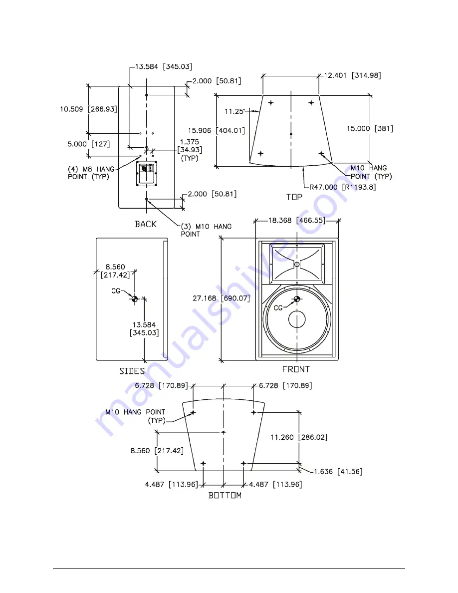
Page 36: ...Community VERIS Series Operation and Installation Manual Page 36 VERIS 15 VERIS 15 Notes The VERIS 15 has a total of 13 x M10 hang points plus 4 x M8 rear mounting points for OmniMount 60 Series inserts ...
Page 37: ...Community VERIS Series Operation and Installation Manual Page 37 VERIS 32 VERIS 32 Notes The VERIS 32 has a total of 13 x M10 hang points plus 4 x M8 rear mounting points for OmniMount 60 Series inserts ...
Page 38: ...Community VERIS Series Operation and Installation Manual Page 38 VERIS 35 VERIS 35 Notes The VERIS 35 has a total of 13 x M10 hang points plus 4 x M8 rear mounting points for OmniMount 60 Series inserts ...
Page 39: ...Community VERIS Series Operation and Installation Manual Page 39 VERIS 210S VERIS 210S Notes The VERIS 210S subwoofer has a total of 8 x M10 hang points 4 on each side ...
Page 40: ...Community VERIS Series Operation and Installation Manual Page 40 VERIS 212S VERIS 212S Notes The VERIS 212S subwoofer has a total of 8 x M10 hang points 4 on each side ...
Page 41: ...lies only to failure of a Community loudspeaker caused by defects in materials and workmanship during the stated warranty period It does not apply to a unit that has been subjected to abuse accident modification improper handling installation or repairs made without factory authorization or by anyone other than authorized Community Field Service Stations This warranty is void if the serial number ...
Page 42: ... extended by the length of time which an owner is deprived of the use of the product Repairs and replacement parts provided under the terms of this warranty shall carry only the remaining portion of the warranty Community reserves the right to change the design of any product from time to time without notice and with no obligation to make corresponding changes in products previously manufactured W...
Page 43: ...Community VERIS Series Operation and Installation Manual Page 43 NOTES ...
Page 44: ...Community Professional Loudspeakers 333 East Fifth Street Chester PA 19013 4511 USA Tel 1 610 876 3400 Fax 1 610 874 0190 www communitypro com 2009 All Rights Reserved 20090804 ...
Page 45: ...atch the color of the enclosure Figure 1 VERIS Loudspeaker and Mounting Yoke VERIS 8 LOUDSPEAKER 10 OR 20 METAL STAND OFF FOR DOWNWARD VERTICAL TILT YOKE BRACKET SERIES OF YOKE MOUNTING HOLES TO VARY THE DISTANCE OF THE ENCLOSURE TO THE MOUNTING SURFACE LONG CORNER OF YOKE SHORT CORNER OF YOKE Warning VERIS rigging fittings are rated at a Working Load Limit of 100 lbs 45 kg with a 10 1 safety marg...
Page 46: ...1 150 29 21 985 25 3 00 76 2 1 969 50 BOTH ENDS SLOT 413 10 5 WIDE X 1 595 40 5 LONG 10 TYP 10 Metal Stand Off 20 Metal Stand Off Each VERIS 6 VERIS 8 VERIS 26 and VERIS 28 loudspeaker includes an optional U shaped 10 metal stand off for vertical mounting of the enclosure at a 10 downward tilt and a 20 metal stand off for vertical mounting of the enclosure at a 20 downward tilt If your installatio...
Page 47: ... within the yoke assembly The installer is solely responsible for determining if the mounting surface is capable of safely supporting the weight load of the loudspeaker for selecting appropriate hardware for the installation and for using the yoke mounting bracket correctly and safely Assembling the yoke and or optional stand offs to the VERIS loudspeaker is relatively straightforward There are fo...
Page 48: ...0 5 WIDE X 1 595 40 5 LONG 4 HOLES 256 6 5 DIA 591 15 TYP 9 374 238 11 1 969 50 15 944 404 98 11 635 295 54 11 045 280 54 9 004 228 69 7 972 202 49 6 940 176 29 5 112 129 85 2 309 58 64 2 899 73 65 2 HOLES 413 10 5 DIA 1 879 47 73 3 879 98 53 20 10 NOTE 0 256 HOLES ACCEPT 1 4 AND 6MM FASTENERS 0 413 HOLES SLOTS ACCEPT 3 8 AND 10MM FASTENERS 0 512 HOLES ACCEPT 1 2 AND 12MM FASTENERS ...
Page 49: ...RUBBER WASHER YOKE BLACK RUBBER WASHER M6 x 30mm HEXBOLT 6mm LOCKWASHER 6mm FLATWASHER M6 x 30mm HEXBOLT 6mm LOCKWASHER 6mm FLATWASHER BLACK RUBBER WASHER YOKE BLACK RUBBER WASHER 6mm FLATWASHER 6mm LOCKWASHER M6 x30 mm HEXBOLT Figure 5 VERIS 6 Yoke Horizontal Mounting Assembly Figure 6 VERIS 6 Yoke Vertical Mounting Assembly ...
Page 50: ...nward Vertical Tilt Mounting Assembly Note the orientation of the yoke with the long corner at the bottom and the correct slot on the yoke onto which to connect the 10 metal stand off in order to achieve a 10 downward vertical tilt M6 x 30mm HEXBOLT 6mm LOCKWASHER 6mm FLATWASHER BLACK RUBBER WASHER 10 METAL STAND OFF 10mm FLATWASHER M10 HEXNUT 10mm FLATWASHER M10 x 30mm HEXBOLT YOKE BLACK RUBBER W...
Page 51: ...LACK RUBBER WASHER 20 METAL STAND OFF 10mm FLATWASHER 10mm LOCKWASHER M10 HEXNUT 10mm FLATWASHER M10 x 30mm LONG HEXBOLT YOKE BLACK RUBBER WASHER 6mm FLATWASHER 6mm LOCKWASHER M6 x 30mm HEXBOLT Note the orientation of the yoke with the short corner at the bottom and the correct slot on the yoke onto which to connect the 20 metal stand off in order to achieve a 20 downward vertical tilt ...
Page 52: ...EPT 3 8 AND 10MM FASTENERS 0 512 HOLES ACCEPT 1 2 AND 12MM FASTENERS 413 10 5mm DIA HOLE 512 13mm DIA HOLE 4 256 6 5 DIA HOLES 4 SLOTS 413 10 5 WIDE X 1 595 40 5 LONG 17 441 443 10 324 262 24 13 132 333 56 12 542 318 56 10 329 262 36 8 721 221 5 7 689 195 3 5 112 129 85 2 309 58 64 2 899 73 65 591 15 TYP 1 969 50 3 879 98 53 1 879 47 73 10 20 X 610 15 5 LONG 2 SLOTS 413 10 5 WIDE ...
Page 53: ...ure 12 VERIS 8 Yoke Vertical Mounting Assembly BLACK RUBBER WASHER 6mm FLATWASHER 6mm FLATWASHER M6 x 30mm HEXBOLT YOKE BLACK RUBBER WASHER M6 x 30mm HEXBOLT 6mm LOCKWASHER 6mm FLATWASHER M6 x 30mm HEXBOLT 6mm LOCKWASHER 6mm FLATWASHER YOKE BLACK RUBBER WASHER 6mm FLATWASHER 6mm LOCKWASHER M6 x 30mm HEXBOLT BLACK RUBBER WASHER ...
Page 54: ...D OFF NOTE ORIENTATION OF YOKE 10 20 M6 x 30mm HEXBOLT 6mm LOCKWASHER 6mm FLATWASHER 10 METAL STAND OFF 10mm FLATWASHER 10mm LOCKWASHER M10 HEXNUT 10mm FLATWASHER M10 x 30mm LONG HEXBOLT YOKE BLACK RUBBER WASHER 6mm FLATWASHER 6mm LOCKWASHER M6 x 30mm HEXBOLT BLACK RUBBER WASHER Note the orientation of the yoke with the long corner at the bottom and the correct slot on the yoke onto which to conne...
Page 55: ...20 METAL STAND OFF 10mm FLATWASHER 10mm LOCKWASHER M10 HEXNUT 10mm FLATWASHER M10 x 30mm LONG HEXBOLT YOKE BLACK RUBBER WASHER 6mm FLATWASHER 6mm LOCKWASHER M6 x 30mm HEXBOLT BLACK RUBBER WASHER Note the orientation of the yoke with the short corner at the bottom and the correct slot on the yoke onto which to connect the 20 metal stand off in order to achieve a 20 downward vertical tilt ...
Page 56: ...5 DIA HOLES 7 SLOTS 413 10 5 WIDE X 1 595 40 5 LONG 9 400 238 76 23 031 584 99 18 706 475 13 18 067 458 9 15 854 402 7 13 138 333 7 11 516 292 5 9 893 251 29 7 360 186 94 5 147 130 73 2 934 74 53 2 722 69 14 1 969 50 3 915 99 45 1 912 48 56 10 20 NOTE 0 256 HOLES ACCEPT 1 4 AND 6MM FASTENERS 0 413 HOLES SLOTS ACCEPT 3 8 AND 10MM FASTENERS 0 512 HOLES ACCEPT 1 2 AND 12MM FASTENERS ...
Page 57: ...gure 18 VERIS 26 Yoke Vertical Mounting Assembly BLACK RUBBER WASHER 6mm FLATWASHER M6 x 30mm HEXBOLT 6mm LOCKWASHER YOKE BLACK RUBBER WASHER 6mm FLATWASHER 6mm LOCKWASHER M6 x 30mm HEXBOLT M6 x 30mm HEXBOLT 6mm LOCKWASHER 6mm FLATWASHER YOKE BLACK RUBBER WASHER 6mm FLATWASHER 6mm LOCKWASHER M6 x 30mm HEXBOLT BLACK RUBBER WASHER ...
Page 58: ...STAND OFF NOTE ORIENTATION OF YOKE 20 10 M6 x 30mm HEXBOLT 6mm LOCKWASHER 6mm FLATWASHER 10 METAL STAND OFF 10mm FLATWASHER 10mm LOCKWASHER M10 HEXNUT 10mm FLATWASHER M10 x 30mm HEXBOLT YOKE BLACK RUBBER WASHER 6mm FLATWASHER 6mm LOCKWASHER M6 x 30mm HEXBOLT BLACK RUBBER WASHER Note the orientation of the yoke with the long corner at the bottom and the correct slot on the yoke onto which to connec...
Page 59: ...ER 20 METAL STAND OFF 10mm FLATWASHER 10mm LOCKWASHER M10 HEXNUT 10mm FLATWASHER M10 x 30mm HEXBOLT YOKE BLACK RUBBER WASHER 6mm FLATWASHER 6mm LOCKWASHER M6 x 30mm HEXBOLT BLACK RUBBER WASHER Note the orientation of the yoke with the short corner at the bottom and the correct slot on the yoke onto which to connect the 20 metal stand off in order to achieve a 20 downward vertical tilt ...
Page 60: ...12 HOLES ACCEPT 1 2 AND 12MM FASTENERS 4 256 6 5 DIA HOLES 8 SLOTS 413 10 5 WIDE X 1 595 40 5 LONG 2 SLOTS 413 10 5 WIDE X 610 15 5 LONG 512 13mm DIA HOLE 413 10 5mm DIA HOLE 26 023 660 99 10 364 263 24 21 084 535 54 21 004 533 49 19 060 484 11 17 035 432 69 15 010 381 25 13 741 349 01 12 283 311 98 11 251 285 77 9 577 243 26 7 364 187 06 5 152 130 85 5 020 127 5 2 939 74 65 1 969 50 3 925 99 7 1 ...
Page 61: ...gure 24 VERIS 28 Yoke Vertical Mounting Assembly BLACK RUBBER WASHER 6mm FLATWASHER 6mm LOCKWASHER M6 x 30mm HEXBOLT YOKE BLACK RUBBER WASHER 6mm FLATWASHER 6mm LOCKWASHER M6 x 30mm HEXBOLT M6 x 30mm HEXBOLT 6mm LOCKWASHER 6mm FLATWASHER YOKE BLACK RUBBER WASHER 6mm FLATWASHER 6mm LOCKWASHER M6 x 30mm HEXBOLT BLACK RUBBER WASHER ...
Page 62: ...ORIENTATION OF YOKE NOTE ORIENTATION OF YOKE 20 10 M6 x 30mm HEXBOLT 6mm LOCKWASHER 6mm FLATWASHER 10 METAL STAND OFF 10mm FLATWASHER 10mm LOCKWASHER M10 HEXNUT 10mm FLATWASHER M10 x 30mm HEXBOLT YOKE 6mm FLATWASHER 6mm LOCKWASHER M6 x 30mm HEXBOLT BLACK RUBBER WASHER Note the orientation of the yoke with the long corner at the bottom and the correct slot on the yoke onto which to connect the 10 m...
Page 63: ...HER 20 METAL STAND OFF 10mmFLATWASHER 10mm LOCKWASHER M10 HEXNUT 10mm FLATWASHER M10 x 30mm HEXBOLT YOKE BLACK RUBBER WASHER 6mm FLATWASHER 6mm LOCKWASHER M6 x 30mm HEXBOLT BLACK RUBBER WASHER Note the orientation of the yoke with the short corner at the bottom and the correct slot on the yoke onto which to connect the 20 metal stand off in order to achieve a 20 downward vertical tilt ...
Page 64: ...l and vertical mounting at 0 the stand offs are not needed 3 Before installing the loudspeaker in the yoke the yoke or yoke and metal stand off assembly should first be attached to the mounting surface No hardware is provided for this purpose Such hardware must be supplied by the installer and should be rated for the weight load of the enclosures The installer is solely responsible for determining...