background image

 User Guide

Advanced Configuration                                                                                                 

SYSTIMAX

 AirSPEED

 AP541

  User Guide

49

Wireless Distribution System (WDS) Sub-tab

A Wireless Distribution System (WDS) creates a link between two 802.11a, 802.11b, or 802.11b/g APs over their radio 
interfaces. This link relays traffic from one AP that does not have Ethernet connectivity to a second AP that has 
Ethernet connectivity. WDS allows you to configure up to six (6) point-to-point links between Access Points.

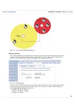
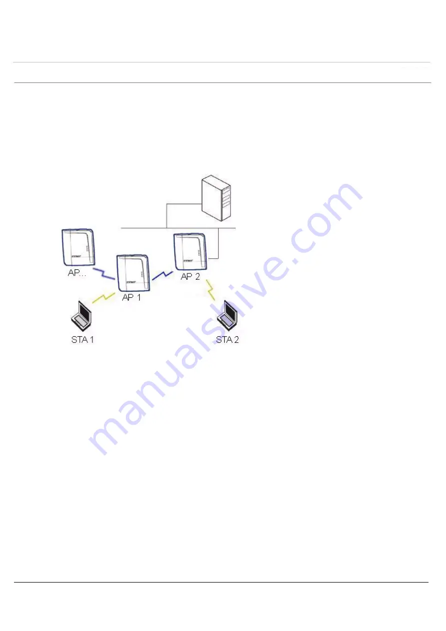
 In the WDS example below, AP 1 and AP 2 communicate over a WDS link (represented by the blue line). This link 
provides Client 1 with access to network resources even though AP 1 is not directly connected to the Ethernet 
network. Packets destined for or sent by the client are relayed between the Access Points over the WDS link.

Figure 4-14  WDS Example

Bridging WDS

Each WDS link is mapped to a logical WDS port on the AP. WDS ports behave like Ethernet ports rather than like 
standard wireless interfaces: on a BSS port, an Access Point learns by association and from frames; on a WDS or 
Ethernet port, an Access Point learns from frames only. When setting up a WDS, keep in mind the following:

There are separate security settings for clients and WDS links. The same WDS link security mode must be 
configured (currently we only support none or WEP) on each Access Point in the WDS and the same WEP key 
must be configured.

The WDS link shares the communication bandwidth with the clients. Therefore, while the maximum data rate for 
the Access Point's cell is 54 Mbits/s (802.11a, 802.11g only, or 802.b/g modes) or 11 Mbits/s (802.11b only mode), 
client throughput will decrease when the WDS link is active. 

If there is no partner MAC address configured in the WDS table, the WDS port remains disabled.

Each WDS port on a single AP should have a unique partner MAC address. Do not enter the same MAC address 
twice in an AP’s WDS port list.

Each Access Point that is a member of the WDS must have the same Channel setting to communicate with each 
other.

If your network does not support spanning tree, be careful to avoid creating network loops between APs. For 
example, creating a WDS link between two Access Points connected to the same Ethernet network will create a 
network loop (if spanning tree is disabled). For more information, refer to the 

Spanning Tree Sub-tab

 section.

Summary of Contents for SYSTIMAX AirSPEED AP541

Page 1: ......

Page 2: ...l Enhancing Antenna Description 17 Antenna Diversity Options 17 Prerequisites for AP Configuration Only 17 Product Package 18 System Requirements 18 Regulatory Compliance and Safety Instructions 18 Initialization 19 ScanTool 19 ScanTool Instructions 19 Setup Wizard 21 Setup Wizard Instructions 21 Download the Latest Software 24 Setup your TFTP Server 24 Download Updates from your TFTP Server using...

Page 3: ...ab 41 Operational Mode 42 Super Mode and Turbo Mode 42 IEEE 802 11D Support for Additional Regulatory Domains 42 Configuring 802 11d Support 42 TX Power Control 43 Wireless Interface Sub tab 802 11a b g radio 44 Dynamic Frequency Selection DFS 46 RTS CTS Medium Reservation 46 Wireless Service Status 46 Multicast Rate 47 Ethernet Sub tab 48 Wireless Distribution System WDS Sub tab 49 Management Tab...

Page 4: ...TCP UDP Port 69 Adding TCP UDP Port Filters 69 Editing TCP UDP Port Filters 69 Alarms Tab 70 Groups Sub tab 70 Severity Levels 72 Alarm Host Table Sub tab 73 Syslog Sub tab 73 Setting Syslog Event Notifications 73 Configuring Syslog Event Notifications 74 Rogue Scan 75 Multi Band Scanning 75 Continuous Scanning Mode 75 Background Scanning Mode 75 RogueScan Data Collection 76 Rogue Scan Sub tab 77 ...

Page 5: ...rarchy 93 VLAN Overview 93 VLAN Workgroups and Traffic Management 95 Traffic Management 95 Typical User VLAN Configurations 95 Typical VLAN Management Configurations 95 VLANs and Security Profiles 97 VLAN Configuration 97 Adding or Modifying a VLAN 97 Security Profiles 98 SecProfiles Sub tab 98 Wi Fi Multimedia WMM Quality of Service QoS 102 Enabling QoS and Adding QoS policies 102 Priority Mappin...

Page 6: ... 129 Troubleshooting Concepts 129 Symptoms and Solutions 130 Connectivity Issues 130 AP Unit Will Not Boot No LED Activity 130 Serial Link Does Not Work 130 Ethernet Link Does Not Work 130 Basic Software Setup and Configuration Problems 130 Lost AP Telnet or SNMP Password 130 Client Computer Cannot Connect 130 AP Has Incorrect IP Address 130 HTTP browser or Telnet Interface Does Not Work 131 HTML ...

Page 7: ...ing the Serial Port Cable 137 Initializing the IP Address using CLI 137 Related Applications 139 RADIUS Authentication Server 139 TFTP Server 139 A Using the Command Line Interface CLI 140 General Notes 140 Prerequisite Skills and Knowledge 140 Notation Conventions 140 Important Terminology 140 Navigation and Special Keys 141 CLI Error Messages 141 Command Line Interface CLI Variations 141 Bootloa...

Page 8: ...Network Name and VLAN Pairs and Profiles 154 Download an AP Configuration File from your TFTP Server 154 Backup your AP Configuration File 154 Set up Auto Configuration 155 Other Network Settings 155 Configure the AP as a DHCP Server 155 Configure the DNS Client 156 Configure DHCP Relay 156 Configure DHCP Relay Servers 156 Maintain Client Connections using Link Integrity 156 Change your Wireless I...

Page 9: ...eters 177 SSH Parameters 178 Auto Configuration Parameters 179 TFTP Server Parameters 179 IP Access Table Parameters 179 Filtering Parameters 180 Ethernet Protocol Filtering Parameters 180 Static MAC Address Filter Table 180 Proxy ARP Parameters 181 IP ARP Filtering Parameters 181 Broadcast Filtering Table 181 TCP UDP Port Filtering 181 Alarms Parameters 182 SNMP Table Host Table Parameters 182 Sy...

Page 10: ... File 192 CLI Batch File Format and Syntax 192 Sample CLI Batch File 192 Reboot Behavior 193 CLI Batch File Error Log 193 B ASCII Character Chart 194 C Specifications 195 Software Features 195 Number of Stations per BSS 195 Management Functions 195 Advanced Bridging Functions 196 Medium Access Control MAC Functions 196 Security Functions 196 Network Functions 197 Advanced Wireless Functions 197 Ha...

Page 11: ...Contents SYSTIMAX AirSPEED AP541 User Guide 11 802 11a 201 802 11g 202 ...

Page 12: ...potential damage to hardware or loss of data and tells you how to avoid the problem Introduction to Wireless Networking An Access Point AP is a device used to extend the existing Ethernet network structured cabling to mobile clients i e laptops PDAs enabling mobility productivity collaboration and flexibility Mobile clients can connect to a single Access Point or move between multiple Access Point...

Page 13: ...unicate see Interfaces Tab All Access Points and clients must have matching security settings to communicate The Access Points cells should overlap to ensure that there are no gaps in coverage and to ensure that the roaming client will always have a connection available The AP541 when set to operate in 802 11b g mode operates in the 2 4 GHz band and offers greater range but less bandwidth 11 Mbits...

Page 14: ...he network HTTP HTTPS Interface Command Line Interface SNMP Management HTTP HTTPS Interface The HTTP Interface Web browser Interface provides easy access to configuration settings and network statistics from any computer on the network You can access the HTTP Interface over your LAN switch hub etc over the Internet or with a crossover Ethernet cable connected directly to your computer s Ethernet P...

Page 15: ...tity could alter an in transit message generated by an authorized entity in such a way as to effect unauthorized management operations including the setting of object values The essence of this threat is that an unauthorized entity could change any management parameter including those related to configuration operations and accounting Masquerade Management operations that are not authorized for so...

Page 16: ...ains a single embedded 802 11a b g radio The unit is software programmable to operate in one of four modes 802 11b mode 802 11g mode 802 11b g mode or 802 11a mode SYSTIMAX recommends powering the AirSPEED AP541 with Power over Ethernet 802 3af alternatively an external DC power source using the power cord may be used to power the device The AirSPEED AP541 includes a power jack a 10 100 base T Eth...

Page 17: ...ress that is valid on your network HTTP Password Each Access Point requires a read write password to access the web interface The default password is public CLI Password Each Access Point requires a read write password to access the CLI interface The default password is public SNMP Read Password Each Access Point requires a password to allow get requests from an SNMP manager The default password i...

Page 18: ...ements To begin using an AP you must have the following minimum requirements A 10Base T Ethernet or 100Base TX Fast Ethernet switch or hub or cross over Ethernet cord At least one of the following IEEE 802 11 compliant devices An 802 11a 802 11b or 802 11b g client device A computer that is connected to the same IP network as the AP and has one of the following Web browsers installed Microsoft Int...

Page 19: ...atically from a network Dynamic Host Configuration Protocol DHCP server during boot up If your network contains a DHCP server you can run ScanTool to find out what IP address the AP has been assigned If your network does not contain a DHCP server the Access Point s IP address defaults to 169 254 128 132 In this case you can use ScanTool to assign the AP a static IP address that is valid on your ne...

Page 20: ... not show up in the Scan List click the Rescan button to update the display If the unit still does not appear in the list see Troubleshooting the AirSPEED AP541 for suggestions Note that after rebooting an Access Point it may take up to five minutes for the unit to appear in the Scan List 8 Do one of the following If the AP has been assigned an IP address by a DHCP server on the network write down...

Page 21: ...zard launches automatically The Setup Wizard provides step by step instructions for how to configure the Access Point s basic operating parameter such as Network Name IP parameters system parameters and management passwords Setup Wizard Instructions Follow these steps to access the Access Point s HTTP interface and launch the Setup Wizard 1 Open a Web browser on a network computer The HTTP interfa...

Page 22: ...ation panel on the left hand side of the screen Click the link that corresponds to the parameters you want to configure to be taken to that particular configuration screen Note that clicking a link in the navigation panel will not submit any changes you made to the unit s configuration on the current page Exit The navigation panel also includes an Exit option Click this link to close the Setup Wiz...

Page 23: ...nt operating channel When Auto Channel Select is disabled you can specify the Access Point s channel If you decide to manually set the unit s channel ensure that nearby devices do not use the same frequency Available Channels vary based on regulatory domain See 802 11a Channel Frequencies Note that you cannot manually set the channel for 802 11a products in Europe see Dynamic Frequency Selection D...

Page 24: ...P Image upgrades The Solarwinds TFTP server software is located on the AirSPEED AP Installation CD ROM You can also download the latest TFTP software from Solarwind s Web site at http www solarwinds net NOTE If a TFTP server is not available in the network you can perform similar file transfer operations using the HTTP interface After the TFTP server is installed Check to see that TFTP is configur...

Page 25: ...plete type reboot 0 and press Enter NOTE See Using the Command Line Interface CLI for more information Additional Hardware Features Installing the AP in the Plenum North America Only Power over Ethernet PoE LED Indicators Installing the AP in the Plenum North America Only In an office building the plenum is the 18 inches of space located above office ceiling tiles used to house the structured cabl...

Page 26: ...rnet PoE integrated module receives 48 VDC over a standard Category 5e 6 Ethernet cable To use PoE you must have a midspan PoE device also known as a power injector connected to the network The cable length between the midspan PoE device and the Access Point should not exceed 100 meters 325 feet The midspan PoE device is not a repeater and does not amplify the Ethernet data signal If connected to ...

Page 27: ...linking Green n a Blinking green indicates transmitting or receiving wireless packets The Ethernet interface is connected at 100 Mbps with traffic Solid Yellow n a n a The Ethernet interface is connected at 10 Mbps with no traffic Blinking Yellow n a n a The Ethernet interface is connected at 10 Mbps with traffic Solid Amber The Bootloader is loading the application software n a n a Blinking Amber...

Page 28: ... Advanced Configuration for information on configuration options that are available within the Access Point s HTTP interface See Monitoring the AirSPEED AP541 for information on the statistics displayed within the Access Point s HTTP interface See Performing Commands for information on the commands supported by the Access Point s HTTP interface See Troubleshooting the AirSPEED AP541 for troublesho...

Page 29: ...ape 6 1 or later 2 If necessary disable the Internet proxy settings For Internet Explorer users follow these steps Select Tools Internet Options Click the Connections tab Click LAN Settings If necessary remove the check mark from the Use a proxy server box Click OK twice to save your changes and return to Internet Explorer 3 Enter the Access Point s IP address in the browser s Address field and pr...

Page 30: ...2 System Status Screen Each section of the System Status screen provides the following information System Status This area provides system level information including the unit s IP address and contact information See System Tab for information on these settings System Alarms System traps if any appear in this area Each trap identifies a specific severity level Critical Major Minor and Informationa...

Page 31: ...ss Control and Accounting Security Overview Configure security features such as MAC Access Control WPA WEP Encryption and 802 1x Configure Rogue Scan Configure up to 16 VLAN and SSID pairs and assign Security and RADIUS Profiles for each pair Wi Fi Multimedia WMM Quality of Service QoS Configure Wi Fi Multimedia Quality of Service parameters and QoS policies Configuring the AP Using the HTTP HTTPS...

Page 32: ...ck the tab that corresponds to the parameter you want to configure For example click Network to configure the Access Point s TCP IP settings The parameters contained in each of the configuration categories are described later in this chapter 7 Configure the Access Point s parameters as necessary After changing a configuration value click OK to save the change 8 Reboot the Access Point for all of t...

Page 33: ...que MAC Media Access Control address for the Access Point s Ethernet interface The MAC address is assigned at the factory Descriptor This is a read only field that reports the Access Point s name serial number current image software version and current bootloader software version Up Time This is a read only field that displays how long the Access Point has been running since its last reboot Figure...

Page 34: ...lphanumeric or hyphen characters are allowed The name cannot start or end with a hyphen The name cannot start with a digit The number of characters has to be 63 or less Currently the system name length is limited to 32 bytes Image upgrades could cause the system to boot with an older system name format that is not DNS compliant To prevent problems with dynamic DNS after an image upgrade the system...

Page 35: ...tab IP Configuration Sub tab This tab is used to configure the internet TCP IP settings for the Access Point These settings can be either entered manually static IP address subnet mask and gateway IP address or obtained automatically dynamic The DNS Client functionality can also be configured so that host names used for configuring the Access Point can be resolved to their IP addresses Figure 4 4 ...

Page 36: ...IP address of the unit s gateway The gateway IP address will default to 169 254 128 133 if the unit cannot obtain an address from a DHCP server DNS Client If you prefer to use host names to identify network servers rather than IP addresses you can configure the AP to act as a Domain Name Service DNS client When this feature is enabled the Access Point contacts the network s DNS server to translate...

Page 37: ...ake sure there are no other DHCP servers on the network and do not enable the DHCP server without checking with your network administrator first as it could disrupt normal network operation Also the AP must be configured with a static IP address before enabling this feature When the DHCP Server functionality is enabled you can create one or more IP address pools from which to assign addresses to n...

Page 38: ...s Default Lease Time optional The default time value for clients to retain the assigned IP address DHCP automatically renews IP Addresses without client notification This parameter supports a range between 0 and 86400 seconds The default is 86400 seconds Maximum Lease Time optional The maximum time value for clients to retain the assigned IP address DHCP automatically renews IP Addresses without c...

Page 39: ...he DHCP Server IP Address Table the following window is displayed The AP supports the configuration of a maximum of 10 server settings in the DHCP Relay Agents server table At least one server must be configured to enable DHCP Relay Figure 4 7 DHCP Server IP Address Table Add Entries To edit or delete entries in the table click Edit the following window appears Make your changes and click OK ...

Page 40: ... screen Enable Link Integrity Place a check mark in the box provided to enable Link Integrity Poll Interval milliseconds The interval between link integrity checks Range is 500 15000 ms in increments of 500 ms default is 500 ms Poll Retransmissions The number of times a poll should be retransmitted before the link is considered down Range is 0 to 255 default is 5 Target IP Address Entry This entry...

Page 41: ...able 802 11d enables IEEE 802 11d support for additional regulatory domains Refer to the IEEE 802 11D Support for Additional Regulatory Domains and Configuring 802 11d Support sections ISO IEC 3166 1 CountryCode the country regulatory domain where the AP is located Enable TX Power Control enables TX Power Control to control transmit power of 802 11 enabled clients within an IBSS Refer to the TX Po...

Page 42: ...are supported in all regulatory domains However Turbo 802 11a mode is not available in the Japan regulatory domain IEEE 802 11D Support for Additional Regulatory Domains The IEEE 802 11d specification allows conforming equipment to operate in more than one regulatory domain over time IEEE 802 11d support allows the AP to broadcast its radio s regulatory domain information in its beacon and probe r...

Page 43: ...vel is advertised in Beacon and Probe Response frames as the 802 11d maximum transmit power level When an 802 11d enabled client learns the regulatory domain related information from Beacon and Probe Response frames it learns the power level advertised in Beacon and Probe response frames as the maximum transmit power of the regulatory domain and configures itself to operate with that power level A...

Page 44: ...devices 802 11b g mode This is the default mode Use this mode if you want to support a mix of 802 11b and 802 11g devices 802 11 a only mode The radio uses the 802 11a standard only Physical Interface Type Depending on the Operational Mode this field reports For 802 11b mode only 802 11b CCK DSSS 2 4 GHz For 802 11g mode 802 11g OFDM DSSS 2 4 GHz For 802 11b g mode 802 11b g ERP CCK DSSS OFDM 2 4 ...

Page 45: ... See 802 11g Channel Frequencies Transmit Rate Select a specific transmit rate for the AP The values available depend on the Operational Mode Auto Fallback is the default setting it allows the AP to select the best transmit rate based on the cell size For 802 11b only Auto Fallback 1 2 5 5 11 Mbits s Auto Fallback is the default setting it allows the AP unit to select the best transmit rate based ...

Page 46: ...The RTS and CTS packets contain a reservation time to notify other radios including hidden nodes that the medium is in use for a specified period This helps to minimize collisions While RTS CTS adds overhead to the radio network it is particularly useful for large packets that take longer to resend after a collision occurs RTS CTS Medium Reservation is an advanced parameter and supports a range be...

Page 47: ...fferent sizes have different capacities and therefore suit different applications For instance a typical office has many stations that require high bandwidth for complex high speed data processing In contrast a typical warehouse has a few forklifts requiring low bandwidth for simple transactions Cell capacities are compared in the following table which shows that small cells suit most offices and ...

Page 48: ...o duplex the AP negotiates with its switch or hub to automatically select the highest throughput option supported by both sides Figure 4 13 Ethernet Sub tab For best results SYSTIMAX recommends that you configure the Ethernet setting to match the speed and transmission mode of the device the Access Point is connected to such as a hub or switch If in doubt leave this setting at its default auto spe...

Page 49: ...ccess Point learns from frames only When setting up a WDS keep in mind the following There are separate security settings for clients and WDS links The same WDS link security mode must be configured currently we only support none or WEP on each Access Point in the WDS and the same WEP key must be configured The WDS link shares the communication bandwidth with the clients Therefore while the maximu...

Page 50: ...reless backbone follow the steps below for each AP that you wish to include in the Wireless Distribution System 1 Confirm that Auto Channel Select is disabled 2 Write down the MAC Address of the radio that you wish to include in the Wireless Distribution System 3 Open the Wireless Interface Configuration screen 4 Scroll down to the Wireless Distribution System heading Figure 4 15 WDS Configuration...

Reviews: