860543388
Instruction Sheet
www.commscope.com
Page 18 of 19
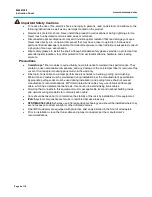
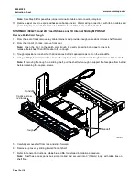
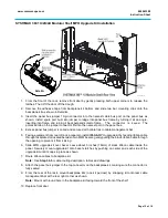
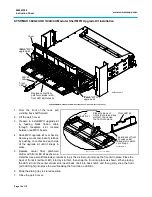
18. Install corrugated tube by snapping onto cable retainers clips on side of shelf.
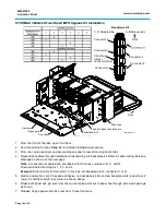
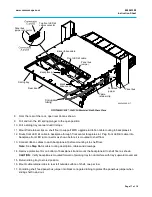
19. Plug each panel bus jumper onto backplane kit and other end to panel bus located on rack.
Note:
The connector is keyed. The polarized tab on the jumper connector fits into the opening in the
header connector on the panel bus.
Important:
Make sure that the jumper connector is fully seated in the header connector on the panel
bus.
20. Slide shelf to stored position and close the patch cover.
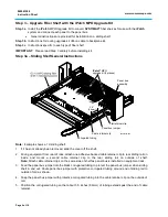
Step 4 – Program the Order of Panels
1. After you have upgraded the shelves in the rack, you should restore power to the
imVision
controller for
the rack and program the order of the panels.
Note:
For instructions, see the
SYSTIMAX
®
imVision
®
Controller User Guide
(860547876).
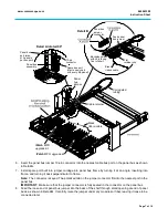
Step 5 – MPO Upgrade Kit Removal
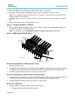
Removing Upgrade Kit on sliding shelves or trays
1. Slide tray or shelf forward.
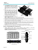
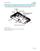
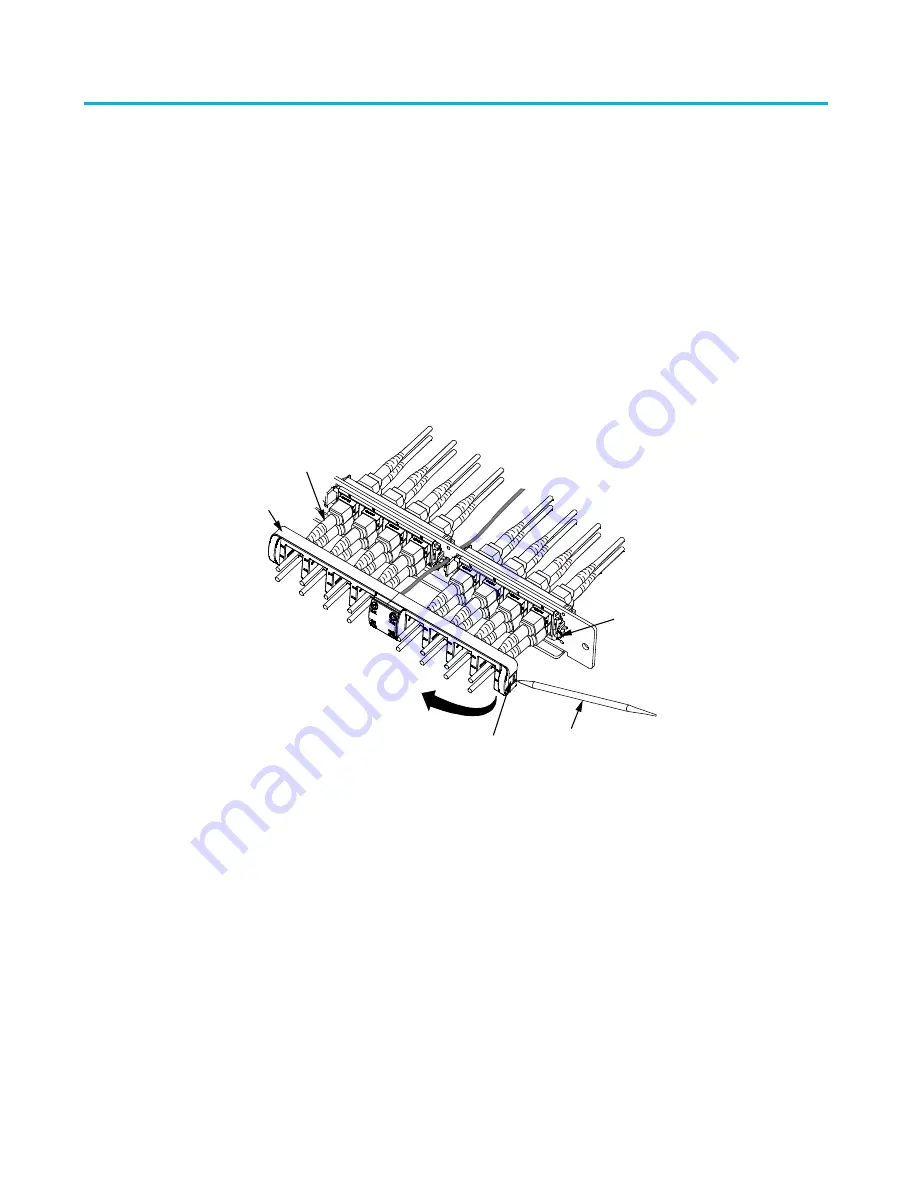
2. Use spudger to pry release tab on one side of the MPO upgrade kit. Using wire tip on spudger, pull tab out
to release kit from bezel latch as shown. Swing away carefully to disengage center and opposite side.
3. Pull MPO upgrade kit forward 2 inches and remove the ribbon cable.
Removing Upgrade Kit on fixed shelves or modular panels
1. Use spudger to pry release tab on one side of the MPO upgrade kit. Using wire tip on spudger, pull tab out
to release kit from bezel latch. Swing away carefully to disengage center and opposite side.
2. Pull MPO upgrade kit forward 2 inches and remove the ribbon cable.
Removal of patchcords
1. Release the MPO connector by pulling on the connector body.
•
A spudger may be used for removal of patchcords.
Release tab
Upgrade kit
Bezel
latch
Patch cord
Spudger
860543388-018

