background image


Page 4 


T750 & T750SE,  Access Point Installation Addendum 


When the frequency band 5150 – 5250 MHz is used outdoors in the U.S.A, the FCC mandates that the energy radiated above 30° from the horizon 

remains below 21 dBm EIRP.  This can be maintained during installation using the following guidance. 


When the device is installed level to the horizon, (i.e. – device perpendicular to the surface of the earth, antenna radome pointing horizontal, parallel to 

the earth), the device operates in compliance with FCC rules without any adjustment of output power. 


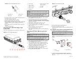
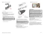
T750 & T750SE  – Antennas 

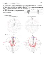
When the device is installed outdoors at an angle above the horizon, it may be 

necessary to reduce output power to insure the energy radiated 

above 30° from the horizon remains under 21 dBm EIRP.  Please see 

table and elevation plots below. 


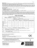
T750 Omni Antenna 3.4dBi 

Vertical Polarity Elevation Pattern 

5150 – 5875 MHz 

Horizontal Polarity Elevation Pattern 

5150 – 5875 MHz: 


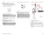
T750SE  Sector Antenna 8dBi


Degree Above Horizon (A) 

Output Power Reduction (dBm) 

A <=12 

0 dBm 

12 < A <15 

1 dBm 

15 <= A < 30 

3 dBm 

30 <= A < 45 

6 dBm 

A > 45 

7dB 

800

-7

2115

-00

1-

A3


Summary of Contents for RUCKUS

Page 1: ...ireless com warranty Before deploying your RUCKUS WIRELESS Access Point verify that all items listed in Package Contents are included in the package If any item is damaged or missing notify your authorized RUCKUS WIRELESS sales representative Also make sure that you have the required hardware and tools Required Hardware and Tools 1 2 13 mm flat blade screwdriver or equivalent No 2 Phillips screwdr...

Page 2: ...gland base 8 Tighten the cable gland dome to 7 in lbs The SFP module is hot swappable and can be removed with fingers or simple tools Connecting the SFP Optic Module Using a Zipcord Cable You can use a zipcord cable to connect to the SFP optic module WARNING The zipcord fiber cable is extremely fragile and must be handled with care NOTE Do not insert the cable gland base grommet dome into the exte...

Page 3: ...tical pole 4 Continue with Mounting the Linkage Bracket to the U Joint Bracket on page 3 Mounting the Linkage Bracket to the U Joint Bracket 1 The linkage bracket attaches to the U joint bracket using an M8 bolt and washer set The linkage bracket is symmetrical and either end can be attached to the U joint bracket NOTE Make sure that linkage bracket is installed with its serrated external tooth lo...

Page 4: ... 6 N m 120 in lbs 3 Continue with Powering the AP with AC on page 7 External Antenna and Cabling Need to be Purchased Separately If the External Antenna option is chosen over the internal sector antenna the External Antenna and Antenna Cable must be purchased separately NOTE Beamflex is not available with external antennas Mounting and Connecting 5 GHZ and 2 5 GHZ External Antennas NOTE Mount the ...

Page 5: ...t covers the connector thread between the cable coupling nut and the base of the connector Make sure that the final wrap is approximately flush with the cable coupling nut and then cut the sealing tape FIGURE 13 Wrapping the Exposed Connector Threads NOTE Cut do not tear the sealing tape If the sealing tape is overstretched it loses its self amalgamating properties Step 4 Wrapping the Internal Lay...

Page 6: ...p Loops Physically mount the AP and antennas at your desired location preferably on the same mounting structure Form 80 mm to 130 mm 3 in to 5 in drip loops with the cables FIGURE 21 Creating Cable Drip Loops Earth Grounding the AP CAUTION Make sure that earth grounding is available and that it meets local and national electrical codes For additional lightning protection use lightning rods and lig...

Page 7: ...n the cable itself 2 in Figure 12 2 Attach the safety cable to the AP 3 in Figure 12 FIGURE 24 Attaching the security cable Troubleshooting CAUTION If required you can reset the AP to its factory default settings by pressing the reset button located inside the PoE IN port Use the tip of a pen or a 3mm flat blade screwdriver to press the reset button Press and hold the reset button for 4 seconds to...

Page 8: ... of the bands 5250 5350 MHz and 5650 5850 MHz and that these radars could cause interference and or damageto LE LAN devices Opération dans la bande 5600 5650 MHz n est pas autorisée au Canada Haute puissance radars sont désignés comme utilisateurs principaux c à utilisateurs prioritaires des bandes 5250 5350 MHz et 5650 5850 MHz et que ces radars pourraient causer des interférences et ou des domma...

Page 9: ...d the user shall cease operatingimmediately until no interference is achieved The said legal communications means radio communications is operated in compliance with the Telecommunications Act The low power radio frequency devices must not be susceptible with the interference from legal communications or ISM radio wave radiated devices 限用物質含有情況標示聲明書 設備名稱 無線網路基地台 型號 型式 T750 T750SE Equipment name Ty...

Page 10: ... requisiti essenziali ed alle altre disposizioni pertinenti stabilite dalla direttiva 2014 53 EU Latviski Latvian Ar šo Ruckus Wireless deklarē ka Radio LAN atbilst Direktīvas 2014 53 EU būtiskajām prasībām un citiem ar to saistītajiem noteikumiem Lietuvių Lithuanian Šiuo Ruckus Wireless deklaruoja kad šis Radio LAN atitinka esminius reikalavimus ir kitas 2014 53 EU Direktyvos nuostatas Nederlands...

Page 11: ...e earth the device operates in compliance with FCC rules without any adjustment of output power T750 T750SE Antennas When the device is installed outdoors at an angle above the horizon it may be necessary to reduce output power to insure the energy radiated above 30 from the horizon remains under 21 dBm EIRP Please see table and elevation plots below T750 Omni Antenna 3 4dBi Vertical Polarity Elev...

Reviews: