Rev H
6
of 6
9.
Carefully
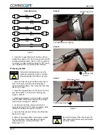
slide the fiber guide at least 76 mm
[3 in.] away from the jack, then carefully route the
fiber out of the slot in the fiber guide. Keep the
protective cover on the jack if not installing the jack
immediately.
To avoid tension on the fiber, it is important to
slide the fiber guide away from the jack before
routing the fiber out of the fiber guide.
10. For workstation jacks, check to make sure that
the fibers are not twisted, then slide the jack boot
over the element housing of the jack until it butts
against the shoulder. See Figure 9.
It is important that the FIBERS ARE NOT
TWISTED before installing the jack boot.
Figure 9
Jack Boot Installed
onto Workstation Jack
3.4. Inspection
Remove the protective cover, and inspect the ferrule
end face for cleanliness using the microscope kit.
3.5. Installation
Refer to Instruction Sheet 408--8844 for instructions
on installing the jacks into the adapter plates, patch
panels, or enclosure or wall box.
DANGER: Never View Active Fiber Signals
4. TESTING
Test the system a ttenuation and polarity using the
applicable test kit listed in Paragraph 3.1.A. Refer to
408--4579 (packaged with the test kit) for instructions
on using the test kit and testing procedures.
5. REPLACEMENT AND REPAIR
Jack kit components are not repairable. Replace any
damaged or defective components.
6. REVISION SUMMARY
Revisions to this instruction sheet include:
•
Updated document to corporate requirements
•
New logo
CAUTION
!
CAUTION
!
408- 8718
•
Rebranded to
CommScope


