background image

3

of 6

Rev H

Figure 2

Green
Brown

A
B

Blue
Orange

Red
Black

Slate
White

Rose
Aqua

Yellow
Violet

Panel Workstation

A
B

A
B

A
B

A
B

A
B

B
A

B
A

B
A

B
A

B
A

B
A

4. Clean the stripped portion of the fiber with an

alcohol fiber wipe or lint--free tissue moistened with

isopropyl alcohol greater than 91% (99% preferred)

to remove the fiber coating residue. DO NOT touch

the stripped portion of the fiber after cleaning.

B. Cleaving the Fiber

Fibers must be terminated as soon as the

cleaving and inspection process is complete;

otherwise, damage to the fibers could result.

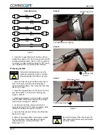
1. Open the fiber clamp of the fiber optic cleaver.

Press the button, and slide the carriage back

(toward the fiber clamp). Then move the fiber slide

back until it stops.

2. Place the stripped fiber into the slot so that the

end of the buffer is at the 6--mm marking. See

Figure 3, Detail A.

3. While applying pressure on the buffer, carefully

slide the fiber slide forward (toward the carriage)

until it stops. See Figure 3, Detail B.

4. Gently close the fiber clamp, and slide the

carriage forward. DO NOT touch the button while

sliding the carriage. See Figure 3, Detail C.

5. Open the fiber clamp, and move the fiber slide

back until it stops.

6. Remove the cleaved fiber, and properly dispose

of the scrap fiber. If the fiber does not cleave,

repeat the process starting with Step 3 of

Paragraph 3.2.A.

Figure 3

Detail B

Detail C

Stripped Fiber in Slot

End of Buffer at 6--mm Marking

Slide Fiber Slide

Forward

Slide Carriage Forward

Fiber Clamp Closed

Be careful to dispose of fiber ends properly. The

fibers create slivers that can easily puncture skin

and cause irritation.

CAUTION

!

CAUTION

!

408- 8718

Detail B

Summary of Contents for MT- RJ 6278414 Series

Page 1: ... 62 and Size XG 50 125 is indicated as XG Except 12 Figure 1 1 INTRODUCTION The MT RJ jack kits listed in Figure 1 are designed to terminate 900 m tight buffered optical fiber The jacks must be used with 125 m multimode fiber optic cable only Read these instructions thoroughly before assembling the jack kits These jack kits cannot be used with build up tubes loose tube fiber easy strip fiber fan o...

Page 2: ...llow the operating instructions 408 series packaged with the tools and safety guidelines packaged with the materials A Required Fiber Optic Combination Strip Tool 1278947 1 408 4577 or 1754708 1 Micro Strip Strip Tool 492109 2 for 900 m buffered fiber Alcohol Fiber Wipe Packet 501857 2 or lint free tissues and isopropyl alcohol greater than 91 99 preferred Fiber Optic Cleaver 1871696 1 408 10086 T...

Page 3: ...ops 2 Place the stripped fiber into the slot so that the end of the buffer is at the 6 mm marking See Figure 3 Detail A 3 While applying pressure on the buffer carefully slide the fiber slide forward toward the carriage until it stops See Figure 3 Detail B 4 Gently close the fiber clamp and slide the carriage forward DO NOT touch the button while sliding the carriage See Figure 3 Detail C 5 Open t...

Page 4: ... the jack on a clean flat surface the protective cover helps to keep the jack stabilized slide the fiber guide onto the back of the jack See Figure 4 The fiber guide is marked with the fiber size Make sure that the marking on the fiber guide corresponds with the fiber size being used Figure 4 Fiber Guide Jack Protective Cover 2 With the handle of the actuation key pointed toward the top of the jac...

Page 5: ... to confirm that the fiber is fully inserted into the fiber hole When the fiber is properly inserted the laser or LED light will diminish in the target area of the jack Refer to Figure 8 If using the visual fault locator avoid contamination to the ferrule end face Make sure that the protective cover remains clean when removed and then before proceeding re install the protective cover onto the jack...

Page 6: ... 9 Jack Boot Installed onto Workstation Jack 3 4 Inspection Remove the protective cover and inspect the ferrule end face for cleanliness using the microscope kit 3 5 Installation Refer to Instruction Sheet 408 8844 for instructions on installing the jacks into the adapter plates patch panels or enclosure or wall box DANGER Never View Active Fiber Signals 4 TESTING Test the system a ttenuation and ...

Reviews: