


M0201ANC_uc
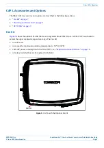
CommScope Era
™
Fiber Low Power Carrier Access Point Installation Guide
© June 2019 CommScope, Inc.
Page 17
Plan and Prepare for a Fiber CAP L Installation
Determine the Power Consumption of the CAP L
Use the power consumption matrix in
to calculate power consumption for a Fiber CAP L, where
•
the consumption numbers are at the CAP L power inputs and do not account for feed losses
•
the maximum consumption numbers in
do not include the power consumed by any attached
auxiliary devices. Both CAP L power consumption and auxiliary device power must be included when
calculating feed losses.
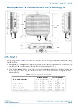
Table 7.
CAP L Power Consumption
Configuration
Voltage Range (V) Typical Power (W) Maximum Power (W)
Fiber CAP L without Fan Kit
1, 2
36 - 60
92
102
Fiber CAP L with Fan Kit
1, 2
36 - 60
95
107
1
Does not include consumption of optional local DC supply.
2
Optical unit does not include SFP+ Module consumption. Can support up to 3W (more with engineering consultation)
maximum total SFP+ Module consumption. Typical installation (sufficient for SM up to 10km or MM) would be 0.8W
typical, 1.0W max for each SFP+ Module.
Determine the CAP L Installation Site
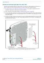
When deciding on a suitable mounting site, observe the following rules; refer also to
.
•
The Fiber CAP L is suitable for indoor installation.
•
CommScope recommends that a Fiber CAP L be installed outdoors only if it has a Fan Kit.
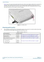
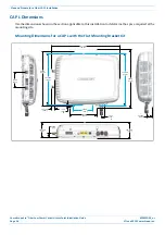
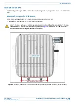
The following sections provides weight and dimension requirements needed to determine the best
installation site for the Fiber CAP L.