background image


 D701-0006 


www.commscope.com 
© 2016 CommScope, Inc. All rights reserved. 
Visit our website at www.commscope.com or contact your local CommScope representative or BusinessPartner for more information. 
All trademarks identified by ® or ™ are registered trademarks or trademarks, respectively, of CommScope, Inc. D701-0006  D (10/16)                             Page 6 of 7 
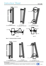


Detail 'A'

Detail 'B'

Torque=28Nm

Torque=95Nm

Torque=38Nm

Torque=28Nm

Torque=95Nm

Torque=38Nm


Figure 6. Setting mechanical uptilt 


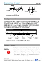
Labelling of Antenna Beams 

 
This antenna radiates 5 beams. As mentioned in connection with tilting of the antenna, the beams 
point downwards relative to the front face of the antenna at an angle of 6°.  In the horizontal plane, 
the beams are at azimuth angles of -40° (i.e. 40° to the left of boresight when looking at the 
antenna from the rear), -20°, 0°, +20°, +40° (i.e. 40° to the right of boresight when looking at the 
antenna from the rear).  There are 10 connectors to the antenna, one for each beam of the antenna 
at a polarization of +45° and one for each beam at a polarization of -45°. 
The pairs of connectors for each beam direction are shown in Figure 7. 
 

+ 40°

POLAR
 + 45°

POLAR
 - 45°

+ 20°

POLAR
 + 45°

POLAR
 - 45°

POLAR
 + 45°

POLAR
 - 45°

- 20°

POLAR
 + 45°

POLAR
 - 45°

- 40°

POLAR
 + 45°

POLAR
 - 45°


Figure 7. Arrangement of connectors on the base of the antenna.


Operation of Antennas 


RF Cable  
Connection 


The 7-16 female connectors fitted to the antenna are designed to fit jumper 
cables with a standard 7-16 RF male connector. After ensuring both mating 
connectors are dry push the male connector in and tighten the connector 
coupling to 23 – 28 Nm (17 -21 ft.lb).  
If  needed  or  as  required  by  local  procedures  a  weatherproofing  kit  may 
then be fitted to the connection.  
If  the  RF  connectors  are  tightened  beyond  the  recommend  torque  the  RF 
connection to the antenna may be damaged. 


+40 

º

Beam 

pointing 

+20 

º

Beam 

pointing 

º

Beam 

pointing 

-20

º

Beam 

pointing 

-40

º

Beam 

pointing 

Summary of Contents for 5UPX0805F

Page 1: ...ired to assist in the correct installation of CommScope Multi Beam Panel Antennas The following symbols can be found next to text outlining important information Please follow the procedure marked with this symbol precisely Non compliance may lead to damage of the product Handy tips when installing product Unpacking Make sure that the antenna and the accessory items listed below are provided and h...

Page 2: ...ructions Fixed Downtilt Mounting Kit F 042 GL E Assemble both mounting brackets to the antenna as per Figures 1 2 3 of this document Attach the mounting kit assembly to the antenna before trying to clamp the brackets to the pole The clamp brackets can clamp pipe diameters between 75 mm 3 115 mm 4 5 For typical installations the minimum recommended pipe diameter is 85 mm 3 3 Figure 1 Correctly Asse...

Page 3: ...ll trademarks identified by or are registered trademarks or trademarks respectively of CommScope Inc D701 0006 D 10 16 Page 3 of 7 40 POLAR 45 POLAR 45 20 POLAR 45 POLAR 45 0 POLAR 45 POLAR 45 20 POLAR 45 POLAR 45 40 POLAR 45 POLAR 45 Torque 95Nm Torque 38Nm Torque 28Nm Figure 2 Fixed Downtilt Mounting Bracket Assembled to Antenna pole Figure 3 Fixed Downtilt Mounting Bracket Exploded Assembly ...

Page 4: ... against the mounting pole as shown in Figure 5 or Figure 6 The first hole is for 2 mechanical downtilt with each consecutive hole resulting in an increased inclination of 2 3 When the tilt arm is used in the upper antenna bracket as shown in Figures 5 the mechanical tilt can be set to 0 or to any angle from 2 to 12 in 2 steps The electrical beams emerge from the front of the antenna with a 6 elec...

Page 5: ...f CommScope Inc D701 0006 D 10 16 Page 5 of 7 976 85 NOMINAL 6 Downtilt 0 mechanical 6 electrical 12 Downtilt 6 mechanical 6 electrical 18 Downtilt 12 mechanical 6 electrical See Detail B See Detail A Torque 28Nm Torque 95Nm Torque 38Nm Detail A Detail B Torque 28Nm Torque 95Nm Torque 38Nm Figure 5 Setting mechanical downtilt 6 Downtilt 0 mechanical 6 electrical 0 Downtilt 6 mechanical 6 electrica...

Page 6: ...sight when looking at the antenna from the rear There are 10 connectors to the antenna one for each beam of the antenna at a polarization of 45 and one for each beam at a polarization of 45 The pairs of connectors for each beam direction are shown in Figure 7 40 POLAR 45 POLAR 45 20 POLAR 45 POLAR 45 0 POLAR 45 POLAR 45 20 POLAR 45 POLAR 45 40 POLAR 45 POLAR 45 Figure 7 Arrangement of connectors o...

Page 7: ...ll trademarks identified by or are registered trademarks or trademarks respectively of CommScope Inc D701 0006 D 10 16 Page 7 of 7 Revision Changes Date A First Release 2011 06 28 B More clearly Define the Recommended Installation Requirements and Warnings Changed drawing template to COMMSCOPE 2013 07 25 C Changed drawing template to latest 2016 08 16 D Replace Argus with CommScope 2016 10 31 ...

Reviews: