LE-575 User’s Manual
59
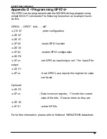
Appendix D <Programming GPIO’s>
The GPIO’can be programmed with the MSDOS debug program using
simple IN/OUT commands.The following lines show an example how to
do this.
GPIO0…..GPIO7 bit0……bit7
-o 2 E 87 ;enter configuration
-o 2E 87
-o 2E 07
-o 2F 09 ;enale GPIO function
-o 2E 30
-o 2F 02 ;enable GPIO configuration
-o 2E F0
-o 2F xx ;set GPIO as input/output; set ‘1’ for input,’0’for
output
-o 2E F1
-o 2F xx ;if set GPIO’s as output,in this register its value
can be set
Optional :
-o 2E F2
-o 2F xx ; Data inversion register ; ‘1’ inverts the current
valus of the bits ,’0’ leaves them as they are
-o 2E 30
-o 2F 01 ; active GPIO’s
For further information, please refer to Winbond W83627DHG datasheet.
Summary of Contents for LE-575
Page 1: ...LE 575 5 25 inch Embedded Miniboard User s Manual Edition 1 0 2009 08 18...
Page 7: ...LE 575 User s Manual 7 The Page is Left For Blank...
Page 11: ...LE 575 User s Manual 11 1 3 Mechanical Drawing...
Page 14: ...LE 575 User s Manual 14 RJ45_4 3 2 1 CF COM1 USB CRT DC_2P 1 11 0 31...
Page 41: ...LE 575 User s Manual 41 This Page is Left For Blank...
Page 45: ...LE 575 User s Manual 45 This Page is Left for Blank...
Page 47: ...LE 575 User s Manual 47 This Page is Left for Blank...
Page 52: ...LE 575 User s Manual 52 This Page is Left for Blank...
Page 54: ...LE 575 User s Manual 54 This Page is Left for Blank...
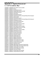
Page 55: ...LE 575 User s Manual 55 Appendix C System Resources C 1 I O Port Address Map...
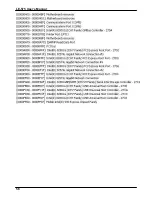
Page 56: ...LE 575 User s Manual 56...
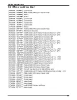
Page 57: ...LE 575 User s Manual 57 C 2 Memory Address Map...


