i
nsTallaTion
i
nsTrucTions
U S C U S T O M E R S U P P O R T 1 - 8 8 8 - 6 2 2 - 2 3 7 7 | W W W. C O M M A N D A C C E S S . C O M | C A C U S T O M E R S U P P O R T 1 - 8 5 5 - 8 2 3 - 3 0 0 2
Note: For AHT4/5 & PD11’s purchased after 2015 only.
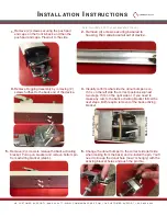
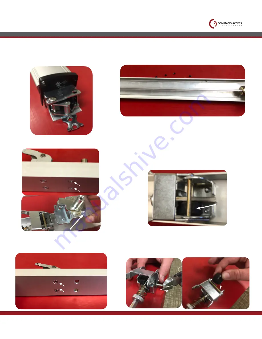
Remove (2) screws securing the push pad
end caps on the front & back, and then the
push pad end caps. Place all to the side
1.
Remove Dogging Assembly by removing (2)
screws furthest to the back end of the device.
3.
Remove (4) screws securing baserail to
housing, then slide baserail out of device.
2.
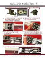
Visually confirm what side the donut bumper is on.
If it is on the left side the correct position,skip next
two steps. If it’s on the right side or if you need to
make any cuts to the back activiting bracket follow the
next steps. Both require removal of the back activing
bracket.
4.
1
2
Remove (2) screws to release the back activating
bracket. Pull up on bracket and remove bottom pin
from activiting bracket (step 6).
5.
1
2
Correct
Front of Device
Back of Device
Change the donut bumper to the correct side (left side
when looking from the back) and re-install the pin. You’ll
need to line up the donut hole (now I’m hungry) with the
activing bracket holes and push the pin thru.
6.


