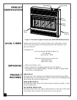


18
101810
4. Wait five (5) minutes to clear out any gas. Then smell for gas, including
near the floor. If you smell gas, STOP! Follow “B” in the safety information
at the top of page 17. If you don’t smell gas, go to the next step.
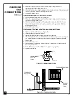
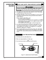
5. Turn control knob counterclockwise
C-clockwise
to the PILOT position. Press
in control knob for five (5) seconds (see Figure 17).
Note:
You may be running this heater for the first time after hooking up
to gas supply. If so, the control knob may need to be pressed in for 30
seconds. This will allow air to bleed from the gas system.
• If control knob does not pop up when released, contact a qualified
service person or gas supplier for repairs.
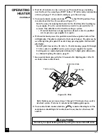
6. With control knob pressed in, push down and release ignitor button. This
will light pilot. The pilot is attached to the front of burner. The pilot can be
seen through the glass panel. If needed, keep pressing ignitor button until
pilot lights.
Note:
If pilot does not stay lit, refer to Troubleshooting, pages 24 through
27. Also contact a qualified service person or gas supplier for repairs.
Until repairs are made, light pilot with match. To light pilot with match,
see Manual Lighting Procedure, page 19.
7. Keep control knob pressed in for 30 seconds after lighting pilot. After 30
seconds, release control knob.
OPERATING
HEATER
Continued
Note:
If pilot goes out, repeat steps 3 through 7. This heater has a safety
interlock system. Wait one (1) minute before lighting pilot again.
8. Turn control knob counterclockwise
C-clockwise
to desired heating level. The
main burner should light. Set control knob to any heat level between HI
and LO.
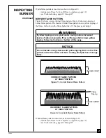
Figure 18 - Pilot
Thermocouple
Ignitor Electrode
Pilot Burner
WARNING ICON
G 001
CAUTION
Do not try to adjust heating levels by using the manual shutoff valve.
Summary of Contents for CGP18TB
Page 31: ...31 101810 NOTES...


