


11
104341
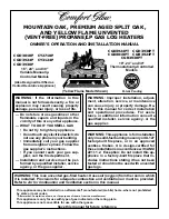
OWNER’S MANUAL
INSTALLING HEATER BASE
ASSEMBLY
WARNING: If installing in a
sunken fireplace, special care is
needed. You must raise the fire-
place floor to allow access to
heater control panel. This will in-
sure adequate air flow and guard
against sooting. Raise fireplace
floor with non-combustible mate-
rial. Make sure material is secure.
CAUTION: Do not pick up
heater base assembly by the
burner. This could damage
heater. Only handle base assem-
bly by grates.
IMPORTANT:
Make sure the heater burn-
ers are level. If heater is not level, heater will
not work properly. For thermostat models,
avoid damage to thermostat bulb. Avoid
nicks or sharp bends in thermostat bulb
wire. Keep thermostat bulb in mounting
bracket.
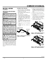
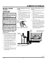
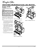
Figure 12 - Attaching Flexible Gas Hose
to Heater Gas Regulator
WARNING: You must secure
this heater to fireplace floor. If
not, heater will move when you
adjust controls. Moving heater
may cause a gas leak.
INSTALLATION
Continued
Installation Items Needed
• hardware package (provided with heater)
• approved flexible gas hose (not provided)
(if allowed by local codes)
• sealant resistant to propane (propane/LP)
gas, not provided
• electric drill with 3/16" drill bit
1.
Apply pipe joint sealant lightly to male
threads of the fitting to be threaded into
gas regulator. Connect approved flex-
ible gas hose to gas regulator of heater
(see Figure 12).
IMPORTANT:
Hold gas regulator with
wrench when connecting flexible gas
hose.
2.
Locate masonry screws in hardware
package.
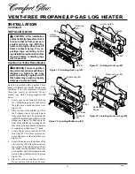
3.
Position heater base assembly in
fireplace.
4.
Mark screw locations through holes in
mounting brackets (see Figure 13). If
installing in a brick-bottom fireplace,
mark screw locations in mortar joint of
bricks.
5.
Remove heater base from fireplace.
6.
Drill holes at marked locations using
3/16" drill bit.
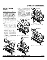
7.
Attach base assembly to fireplace floor
using two masonry screws (in hardware
package) (see Figures 13 and 14).
8.
Connect to gas supply. See Connect-
ing To Gas Supply, page 12.
Figure 13 - Attaching Base Assembly to
Fireplace Floor - Dual Burner Model
Mounting
Bracket
Figure 14 - Attaching Base Assembly to
Fireplace Floor - Single Burner Model
Continued
Heater Gas
Regulator
Flexible Gas Hose
(if allowed by local
codes)
Fitting
Masonry
Screw
Masonry
Screw
Mounting
Bracket
CAUTION: Do not remove the
metal data plates attached to the
heater base assembly. The data
plates contain important warranty
information.


