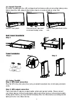
background image


Step 7: Turn on the UPS   
Press the ON/Mute button on the front panel for two seconds to power on the UPS. 

Note: The battery charges fully during the first five hours of normal operation. Do not 
expect full battery run capability during this initial charge period. 
 

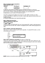
Step 8: Install software 
For optimal computer system protection, install UPS monitoring software to fully configure UPS 
shutdown. Please follow steps below to download and install monitoring software:


1. Go to the website http://www.power-software-download.com 
2. Click ViewPower software icon and then choose your required OS to download the software.   
3. Follow the on-screen instructions to install the software. 
4. When your computer restarts, the monitoring software will appear as an orange plug icon 

located in the system tray, near the clock. 
 
2-4 Battery Replacement 

NOTICE: This UPS is equipped with internal batteries and user can replace the batteries 
without shutting down the UPS or connected loads.(hot-swappable battery design) 
Replacement is a safe procedure, isolated from electrical hazards.   

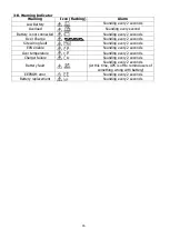
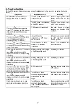
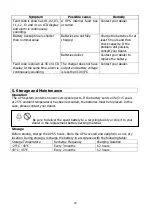
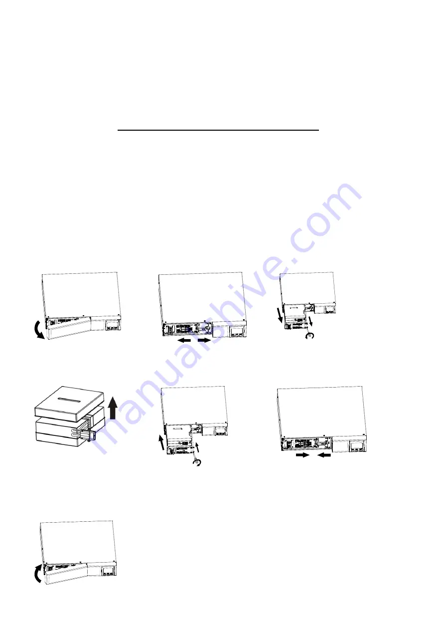
CAUTION!! Consider all warnings, cautions, and notes before replacing batteries.   
Note: Upon battery disconnection, equipment is not protected from power outages. 
 
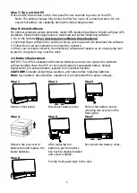
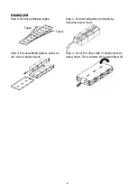
Step 1 

Step 2 

Step 3 


Remove front panel.   

Disconnect battery wires. 

Pull out the battery box by 
removing two screws on the 
front panel.   

Step 4 

Step 5 

Step 7 


Remove the top cover of 
battery box and replace the 
inside batteries.   

After replacing the 
batteries, put the battery 
box back to original location 

and screw it tightly.   

Re-connect the battery wires.   

Step 8 


Put the front panel back to the unit.   

Summary of Contents for Winter 2000

Page 1: ...Winter 2000 3000 Line Interactive Sinewave UPS 2K 3K VA Uninterruptible Power Supply System Version 1 1 User Manual...

Page 2: ...1 Rear Panel View 3 2 2 Install The UPS 4 2 3 Setup The UPS 4 2 4 Battery Replacement 6 2 5 Battery Kit Assembly option 7 3 Operations 9 3 1 Button Operation 9 3 2 LCD Panel 9 3 3 Audible Alarm 10 3 4...

Page 3: ...er them Do not connect domestic appliances such as hair dryers to UPS output sockets The UPS can be operated by any individuals with no previous experience Connect the UPS system only to an earthed sh...

Page 4: ...must be kept well away from the batteries Caution risk of electric shock The battery circuit is not isolated from the input voltage Hazardous voltages may occur between the battery terminals and the...

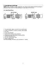
Page 5: ...ar Panel View 3K IEC Type 2K IEC Type 1 Programmable outlets connect to non critical loads 2 Output receptacles connect to mission critical loads 3 AC input 4 Input circuit breaker 5 Network Fax Modem...

Page 6: ...nstallation Step 1 Step 2 Tower Installation Step 1 Step 2 Step 3 2 3 Setup The UPS Step 1 UPS input connection Plug the UPS into a two pole three wire grounded receptacle only Avoid using extension c...

Page 7: ...e time Step 4 Network connection Network Fax Phone surge port Connect a single modem phone fax line into surge protected IN outlet on the back panel of the UPS unit Connect from OUT outlet to the equi...

Page 8: ...monitoring software will appear as an orange plug icon located in the system tray near the clock 2 4 Battery Replacement NOTICE This UPS is equipped with internal batteries and user can replace the b...

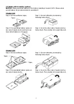
Page 9: ...3 Put assembled battery packs on one side of plastic shells and insert one more defect battery on the space Step 4 Cover the other side of plastic shell as below chart Then battery kit is assembly we...

Page 10: ...tapes Step 2 Connect all battery terminals by following below chart Step 3 Put assembled battery packs on one side of plastic shells Step 4 Cover the other side of plastic shell as below chart Then ba...

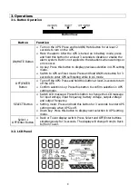
Page 11: ...nter UPS self testing while in AC mode OFF ENTER Button Turn off the UPS Press and hold this button at least 2 seconds to turn off the UPS Confirm selection key Press this button to confirm selection...

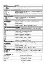
Page 12: ...s that programmable management outlets are working Mode operation information Indicates the UPS connects to the mains Indicates the battery is working Indicates the bypass circuit is working Indicates...

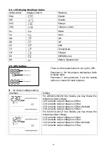
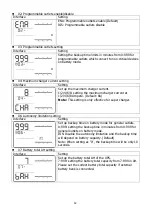
Page 13: ...ameter 2 and parameter 3 are the setting options or values for each program 01 Output voltage setting Interface Setting For 208 220 230 240 VAC models you may choose the following output voltage 208 p...

Page 14: ...4 6 8 Ampere Default 8A Note This setting is only effective for super charger 06 Autonomy limitation setting Interface Setting Set up backup time on battery mode for general outlets 0 999 setting the...

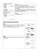
Page 15: ...as EPO logic it will activate EPO function with Pin 1 and Pin 2 in close status DIS Disable the EPO function 00 Exit setting Interface Setting Exit the setting mode Steps for setting programmable outl...

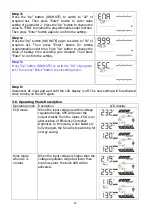
Page 16: ...ep 5 Press Up button ON MUTE to switch to 00 of program list Then press Enter button to exit setting menu Step 6 Disconnect AC input and wait until the LCD display is off The new setting will be activ...

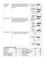
Page 17: ...onds UPS will backup power from battery Standby mode UPS is powered off and no output supply power but still can charge batteries 3 7 Faults Reference Code Fault event Fault code Icon Fault event Faul...

Page 18: ...Sounding every 2 seconds Site wiring fault Sounding every 2 seconds EPO enable Sounding every 2 seconds Over temperature Sounding every 2 seconds Charger failure Sounding every 2 seconds Battery faul...

Page 19: ...seconds The external or internal battery is incorrectly connected Check if all batteries are connected well Fault code is shown as 27 and the icon is lighting on LCD display and alarm is continuously...

Page 20: ...t have output and battery voltage is less than 10V PC Contact your dealer 5 Storage and Maintenance Operation The UPS system contains no user serviceable parts If the battery service life 3 5 years at...

Reviews: