13
7 - CARBURETTOR
- The Aquascooter has a carburettor with two membranes. The first membrane
acts as a pump, drawing the fuel from the tank and into the engine as required.
Faults involving this pump-membrane are extremely rare.
- The second membrane, located in the bottom part, regulates the flow of fuel and
needs to be connected to the external atmospheric pressure so as to regulate
the fuel to suit the engine’s needs. In normal engines that do not run in the water,
this is done with a simple hole in the cover of the membrane. The Aquascooter’s
carburettor has to run in the water, so this system cannot be used. There is
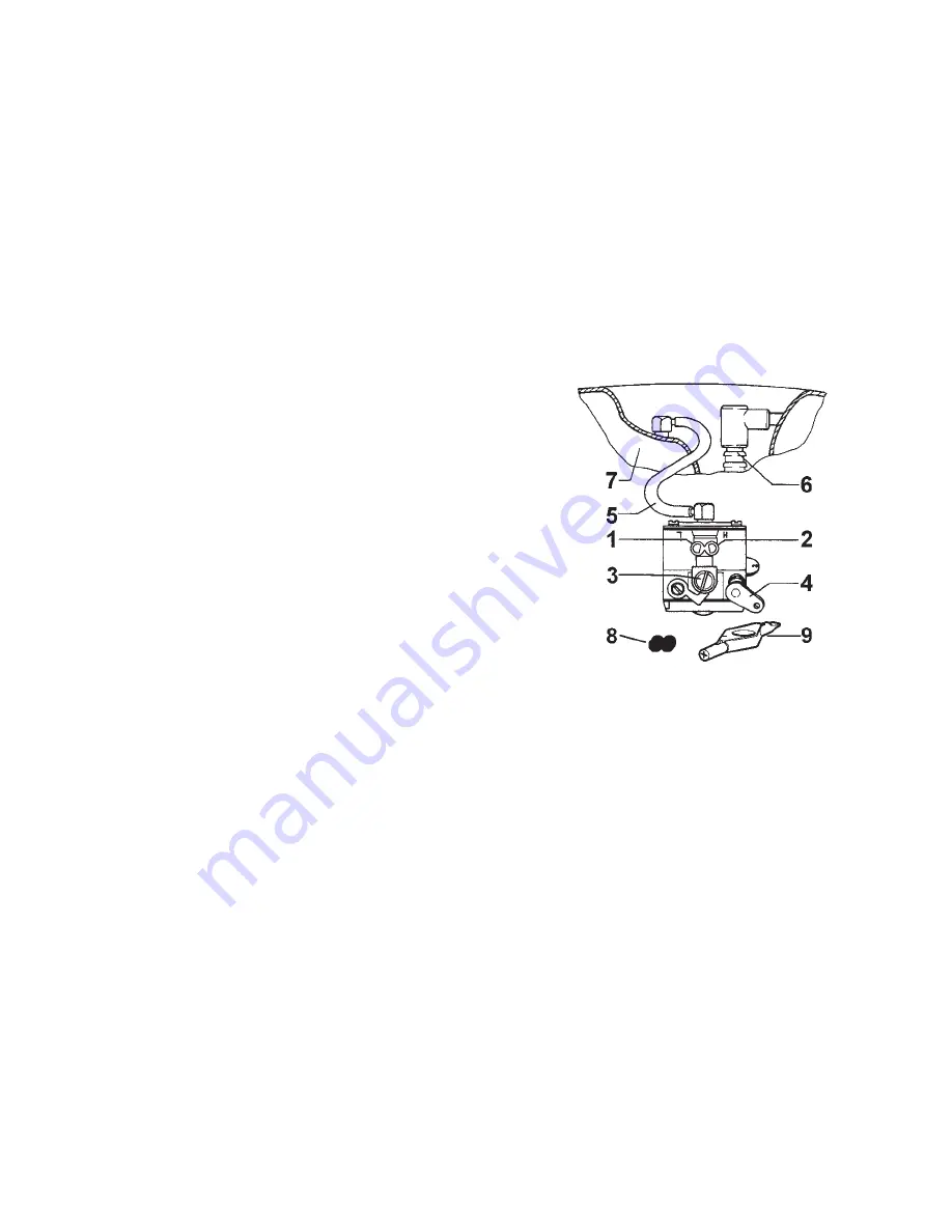
therefore a rubber tube connecting the carburettor to the atmospheric pressure in
the air tank (5, fig.7).
7.1- ADJUSTMENTS.
1 - Idling/Medium rate adjuster screw ( L )
2 turns
2 - Full throttle (H) rpm adjuster screw 1
and 3/4 turns
3 - Idling adjuster screw
4 - “Start and Run” lever
5 - Membrane pressure compensation tube
6 - Spark plug
7 - Air tank
8 - Rubber stopper for closing the carburetor
screws
9 - Adjusting key
- This engine has been designed and built in accordance with CARB-EPA
Exhaust Emission Standards
.
- The Exhaust Emission Control System includes the fuel system, the intake system
and, more importantly, the carburettor:
designed to allow only adjustments of
screws L and H in a preset range established by the manufacturer that
cannot be modified by the user
.
You can only adjust the throttle valve “idling” adjuster screw (3, fig. 7) to regulate
the engine in the water if it stops when idling.
7.2 - WARNING: With the Aquascooter out of the water and the accelerator at full
throttle, the engine must always be abundantly supplied with fuel, otherwise you
will not obtain maximum power in the water.
If faults or fuel problems occur, contact your nearest dealer who can adjust the
relevant screws
L
and H by 1/8 of a turn with a special wrench, to find the optimal
setting and allow the engine to function without stopping in the water.
fig.7


