10
A
B
CN2
CN3
CN4
CN7
1
+
24V
CN1
CN1
C
N
3
2
-
0V
A
U
X
CN7
-
1
C
O
M
CN2
VBAT
1
+
2
N
C
2
R
E
S
E
T
+
-
1
2
C
O
M
N
O
3
2
4
RS232
S
H
IE
L
D
1
C
N
5
5
CN5
R
S
48
5
N
O
6
2
-
3
C
O
M
7
+
A
C
T
I
N
C
8
N
O
9
D
C
O
M
10
A
L
E
R
N
C
11
N
O
12
C
O
M
13
F
A
U
L
N
C
14
N
O
15
C
Legend
A Ethernet
B 1A fuse
C Serial
D I/O board
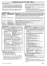
Figure 2-3: IFT-P detector circuit board diagram
Notes:
please refer to appendix B for further information.
2.4 Connection interfaces
The I/O connectors for the IFT-P detector are listed in the table below.
Ethernet
Allows TCP/IP connection with a PC which has VSC or VSM4 installed on it via LAN/WAN.
CN1 – RS232 interface
Pin
Name
Description
2
Receives
Allows serial connection with a PC which has VSC or VSM4 installed on it
Data
for configuration and supervision purposes.
Requires a null-modem cable, for a distance of up to 15 m.
3
Sends
Data
Notes:
5
0V
the null-modem cable must be “female-female”
1, 4, 6, 7, 8, 9
N/C
crossover (TX-RX)
Only intended for local configuration.
Braided strap
Earth
(Shield)
CN2 - Power supply
Pin
Name
Description
1
24VDC
Cable with minimum cross-section 0.75 mm²
W-F/H
24 VDC input for external power supply.
2
0VDC
Notes
please refer to appendix C for further information.
Summary of Contents for IFT-P
Page 1: ...ASPIRATING SMOKE DETECTOR 1 ZONE 2 CHANNELS ART IFT P...
Page 2: ......
Page 4: ...4...
Page 11: ...11...
Page 20: ...20 Figure B 1 Fault relay Normally Closed...
Page 22: ......


