17
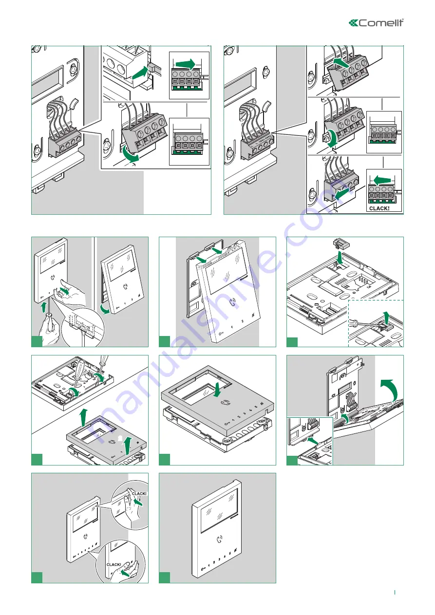
Removing / Fitting the terminal
Fitting upgrade KIT Art. 6734W
3
1
2
L
CFP
(to remove)
+
,-.$
,-.'
7
8
5
4
6
Page 1: ...EN TECHNICAL MANUAL Technical manual for single family KIT Art 8461V Passion Technology Design...
Page 2: ...in proximity to power supply cables 230 400V Do not insert objects or pour liquids into the device Installation mounting and assistance procedures for electrical devices must only be performed by spe...
Page 3: ...28 Programming of door entry phone Art 2638 28 Wiring diagrams 29 KIT 8461V standard single family system Switching on voltage check with system in standby 29 KIT 8461V expansion for two family syste...
Page 4: ...cessoires et mat riaux non d origine Tous les produits sont conformes aux prescriptions des directives 2014 30 UE 2014 35 UE L application du marquage CE atteste cette conformit viter de placer les fi...
Page 5: ...UTP5 cat 5 0 2 mm2 0 5 mm AWG 24 100 m 330 feet 60 m 195 feet 0 28 mm2 0 6 mm AWG 23 100 m 330 feet 60 m 195 feet 0 5 mm2 0 8 mm AWG 20 100 m 330 feet 60 m 195 feet 1 mm2 1 2 mm AWG 17 100 m 330 feet...
Page 6: ...re l apparecchio interrompere l alimentazione per circa 1 minuto To reset the operation after a short circuit cut off mains voltage for about 1 minute Apres un court circuit pour remettre en fonction...
Page 7: ...k release enabled audio enabled system engaged 6 Transparent front panel with label holder in 1 2 4 button versions default 1 button f f To send the call touch the button corresponding to the user you...
Page 8: ...8 Installation 1 2 OPEN 3 1 2 2 1 163 cm 130 cm 5 2 1 CAUTION Tighten properly to avoid leaks 4 COM L LRTE 6 7 optional...
Page 9: ...E JOHN SMITH PETER WHIT 8 9 Labels must be made of non conductive material so as not to compromise the operation of the soft touch buttons Before fixing the screw make sure that you do not need to pro...
Page 10: ...ting LED disabled ON LED lighting of nameholder front panels OFF OFF The lock release relay and the second relay are controlled by a single button e g lock release button OFF lock release activation t...
Page 11: ...ion you want to program as shown in the table on page 11 Reset the configuration of the DIP switches of S1 Code Dip Switch ON Function 1 1 button 1 enabled with call address 1 default 2 2 buttons 1 2...
Page 12: ...ing a generic call address 2 1 example 3 4 5 1 2 3 4B Take note of the DIP switch settings NOTE Fig 3 Set the user code on Dip Switches S1 see table A on page 13 Reset the configuration of the DIP swi...
Page 13: ...74 2 4 7 104 4 6 7 134 2 3 8 164 3 6 8 194 2 7 8 224 6 7 8 15 1 2 3 4 45 1 3 4 6 75 1 2 4 7 105 1 4 6 7 135 1 2 3 8 165 1 3 6 8 195 1 2 7 8 225 1 6 7 8 16 5 46 2 3 4 6 76 3 4 7 106 2 4 6 7 136 4 8 166...
Page 14: ...er code setting see table on page 13 8 S2 Micro switches for programming keys and functions DIP 1 2 3 4 for key function programming DIP 5 6 access to programming DIP 7 for power supply voltage manage...
Page 15: ...led continuous flashing device in programming mode 4 flashes system engaged LED AUDIO 6 steady with call audio activated steady idle automatic answer activated continuous flashing incoming call Lock r...
Page 16: ...16 Installation 1C 1B 1A 4 3 2 6 2 1 5 optional fixing 115 mm 160 mm...
Page 17: ...17 Removing Fitting the terminal Fitting upgrade KIT Art 6734W 3 1 2 L L C F P 1 C F P 2 1 2 3 to remove 3 2 1 2 3 1 2 1 7 8 5 1 1 2 2 2 4 1 2 2 6...
Page 18: ...0000 default Operation Answer incoming call Activation deactivation automatic answer mode Press the soft touch audio activation key to answer incoming call f f Press on the audio activation key for 10...
Page 19: ...o a maximum of 3 internal units For group calls select the desired intercom codes simultaneously max 3 Advanced monitor configuration Programming for intercom call General intercom function allowing c...
Page 20: ...page 13 go to point 3 E g 2 for P3 single family intercom set S2 DIP switches 1 2 3 4 to the combination 1000 or 0011 or 1011 P3 INT set S1 with address 2 in accordance with table B on page 19 go to p...
Page 21: ...internal unit enters audio mode At this point the 2 operators will be communicating with each other Step 2 intercom call programming Operator 1 f f Press the key you want to program to call operator 2...
Page 22: ...ACT set S1 with address 125 in accordance with table A on page 13 go to point 3 3 Press and release the key to be associated with the function the lock release LED lights up a confirmation tone will s...
Page 23: ...E g 1 for P1 self ignition P2 Doctor set S2 DIP switches 1 2 3 4 to the combination 0110 P1 AI P2 D 3 Press and release the keys to which you wish to assign the functions the lock release LED lights u...
Page 24: ...the switchboard 3 times 3 confirmation tones are emitted to change the ringtone for intercom calls made from the internal unit 4 times 4 confirmation tones are emitted to change the floor door call r...
Page 25: ...1 2 3 4 combination Intercom address absent Range function and min max addresses absent Ringtone reset Programming reset Take note of the S2 S1 setting and restore it when programming is complete 1 2...
Page 26: ...he call If the system is not busy The receiver of the call can press the audio key or pick up the handset to communicate with the caller Press the audio button again or hang up the handset to terminat...
Page 27: ...ll toggle between the external units activating alternately the main external unit and the secondary external unit With the switching device Art 1405 it is possible to install only 1 main external uni...
Page 28: ...28 Installation of door entry phone Art 2638 Programming of door entry phone Art 2638 3 2 1 9 8 7 6 5 140 145 cm 115 125 cm 4 Set the user code on Dip Switches U2 as indicated in the table on page 13...
Page 29: ...stem Switching on voltage check with system in standby MNVK 039QC Local lock release button ON 8 5 7 6 4 3 2 1 1234 67 5 8 ON C F P L L C F P 1 2 6721W 6721W BM L L O D E T R NO SE SE NC C M O C 1209...
Page 30: ...all addresses 1 2 see page 11 Local lock release button 8461V ON 8 5 7 6 4 3 2 1 1234 67 5 8 ON C F P L L C F P 1 2 L L O D E T R NO SE SE NC C M O C 1209 L N 110 240V L2 L2 L1 L1 4893 LM LM OUT L IN...
Page 31: ...L L 1216 ON 8 5 7 6 4 3 2 1 1234 67 5 8 ON C F P L L C F P 1 2 LM LM OUT L IN L IN L OUT L 1214 2C LM LM OUT L IN L IN L OUT L 1214 2C C F P L L C F P 1 2 ON 8 5 7 6 4 3 2 1 1234 67 5 8 ON 6721W 6721W...
Page 32: ...r information regarding operating modes please refer to Operation section page 26 Local lock release button N C contact for door open indication Door open indication not available 8461V L L O D E T R...
Page 33: ...not available 8461V L L O D E T R NO SE SE NC C M O C 1209 L N 110 240V L2 L2 L1 L1 4893 1404 L M L M L S L S LP IN MAX ON 8 5 7 6 4 3 2 1 MIN ON 8 5 7 6 4 3 2 1 LP OUT A B JP1 ON 8 5 7 6 4 3 2 1 123...
Page 34: ...216 1404 L M L M L S L S LP IN MAX ON 8 5 7 6 4 3 2 1 MIN ON 8 5 7 6 4 3 2 1 LP OUT A B JP1 ON 8 5 7 6 4 3 2 1 1234 67 5 8 ON C F P L L C F P 1 2 LM LM OUT L IN L IN L OUT L 1214 2C L L 1216 L N 110 2...
Page 35: ...ive manual Local lock release button 8461V L L O D E T R NO SE SE NC C M O C 1209 L N 110 240V L2 L2 L1 L1 4893 C N O C N L L L OUT L IN L IN L OUT LM LM 1214 2C 1256 12 24V AC DC 12V 1200 230V ON 8 5...
Page 36: ...L2 L1 L1 4893 1234 67 5 8 ON 1409 G N D A N I 3 V S 3 2 S V 2 S 1 1 V L L L OUT L OUT IN IN 230V 12V 1200 C F P L L C F P 1 2 ON 8 5 7 6 4 3 2 1 1234 67 5 8 ON S1 S2 A P 6721W 6721W BM MNVK 015QC To b...
Page 37: ...21W BM 6710 S S1 S2 A P MNVK Q21 Additional monitors Art 6721W BM do not include a backplate P 1234 67 5 8 ON 1234 67 5 8 ON CV5 ON 8 5 7 6 4 3 2 1 1234 67 5 8 ON C F P L L C F P 1 2 C F P L L C F P 1...
Page 38: ...P 1 2 6721W 6721W BM 6721W 6721W BM 6710 6721W BM 6710 6721W BM 6710 6721W 6721W S S S S1 S2 A P S1 S2 A P S1 S2 A P S1 S2 A P MNVK Q22 Additional monitors Art 6721W BM do not include a backplate LM L...
Page 39: ...2610 S P F C P F C L L S C P 2 2 P F C L L P F C S S S1 S2 SW1 6228W 6228B 1209 1214 2C SW3 S2 S1 2628 S P F C P F C L L S C P 3 3 2638 6721W 6721W BM MNVK FC L L O D E T R NO SE SE NC C M O C 1209 L...
Page 40: ...release button If there are a number of door entry phones or monitor brackets with the same user code connect the CFP button to one only all the devices will ring simultaneously 20 m MAX Use screened...
Page 41: ...41...
Page 42: ...w w w c o m e l i t g r o u p c o m Via Don Arrigoni 5 24020 Rovetta BG Italy 2nd edition 04 2016 code 2G40001601...