background image


 IMI 66-047

Programming

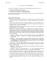
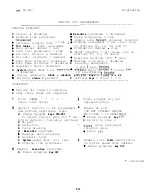
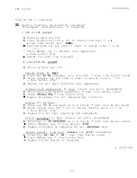
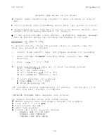
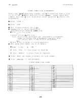
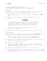
VERIFING TAPE DATA (Requires Data Printer)

To verify previously recorded cassette tape,

 Rewind pre-recorded cassette tape, and prepare recorder

for play-back.

 Press

ITCM * 7 4 6 * ITCM

Start tape playback

 Press program key 
 Printer will print status as follows:

VERIFY COS DATA TAPE
VERIFY TAPE 

 COMPLETE

VERIFY TAPE DATA ERROR

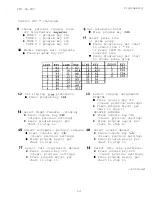
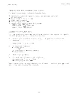
LOADING COS DATA FROM TAPE

-

- -  

  - - -

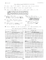
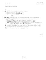
To load previously recorded COS program values into system to replace
current program values, proceed as follows:

2 .

3 .

4 .

5 .

Install pre-recorded cassette tape,

and prepare recorder for

playback

Press ITCM * 7 4 6 * ITCM

To load COS features,

Press HOLD

To load memory dialing numbers,

 Press RECALL

Start tape playback.

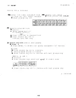
To abort the procedure (if required),

Press ITCM * 7 4 6 * ITCM

 Press program key 

 loading requires approximately 10 minutes.

Station port 

 or 11

will ring when loading is complete.

3-23

Summary of Contents for Executech 2232

Page 1: ...MODEL 2232 HYBRID KEY SYSTEM Coinmhted o U S design lea M busirless commhnieations Change pages 3188 I Ml 66 047 SEPTEMBER 1987 ...

Page 2: ......

Page 3: ......

Page 4: ......

Page 5: ......

Page 6: ......

Page 7: ...m routine maintenance procedures such as the following listed ones but all other servicing must be performed by factory authorized personnel Place or replace any designation strips on the face of the telephone stations Replace the line cord or handset coiled cord OReplace complete stations and station handsets The handset is a special Comdial type Other handset types will not work properly OReloca...

Page 8: ...r must be provided to the telephone company The FCC registration number and the ringer equivalence number of this equipment are provided on the label attached to the KSU The user installer is required to notify the telephone company when final disconnection of this equipment from the telephone company line occurs DUAL REGISTRATION NO I IPICATION _ _ __ __ This equipment can be hardware configured ...

Page 9: ...a service problem occurs first try to determine if the trouble is in the on site system or in the telephone company equipment Disconnect all equipment not owned by the telephone company If this corrects the problem the faulty equipment must not be reconnected to the telephone line until the problem has been corrected Any trouble that causes improper operation of the telephone network may require t...

Page 10: ...radio s receiving antenna and or relocate the KSU the individual telephone stations and the radio or TV with respect to each other If necessary the user should consult the manufacturer or an experienced radio television technician for additional suggestions The user may find the following booklet prepared by the Federal Communications Commission helpful How to Identify and Resolve Radio TV Interfe...

Page 11: ...ocation must be secure and dry and have a d e u a t e ventilation The temperature range of the location must x e within 32 122degrees F O 5U degrees C and the relative humidity must be less than 90 percent non condensing OIf the mounting surface is damp or if it is concrete or masonry material a backboard must be attached to the mounting surface to be used for KSU mounting Suitable mounting backbo...

Page 12: ...U mounting flange and into the mounting surface holes Note that the flange holes are elongated with an enlargement at one end This feature allows the mounting screws to be partially installed in the mounting surface before the cabinets are hung on them The flange holes on the power supply cabinet have an enlargement at the center of the elongated holes to allow the cabinet to be mounted with the p...

Page 13: ... the SYSTEM CHECKOUT instructions given later in this chapter Connections The KSU interface connection for the TELCO or PBX lines is a 50 pin male connector A 25 pair cable properly terminated must be connected from the KSU connector to the demarcation point connector typically a 66M xx connector B To help insure that foreign voltages which could appear on the TELCO lines do not damage the system ...

Page 14: ...le 2 4 and Figure 2 4 A power failure pair is only active during a power failure An industry standard single line telephone such as a type 2500 can be connected to a power failure pair and used to provide communications capability should the AC power to the system be interrupted Station Auxiliary Jack Connections For those stations equipped with an auxiliary jack pins 3 and 4 tip and ring leads of...

Page 15: ...ock The maximum distance between the device and the KSU must not exceed 50 feet Refer to Table 2 4 for connection details When preparing a cable for connection to a data device refer to the manufacturer s manual for the equipment being interfaced and make the following wiring connections l Wire the KSU RD line data from device to KSU to the device TD transmit data output pin Wire the KSU TD data t...

Page 16: ...points are available at the J l and J 2 station connector blocks l One set J l connections provides a dry contact closure whenever any of the TELCO PBX lines connected to the KSU ring l The other set J 2 connections provides a dry contact closure whenever system station port 17 rings These contact closures track the ringing pattern in both cases The contacts are closed during the ringing period an...

Page 17: ...iary Station Interface station port 17 audible contact points are automatically reconfigured as PA enable terminals The contact closure now occurs when PA station port 41 is dialed The normal auxiliary station interface function as discussed previously is disabled as long as station port 41 is a PA station Area Paging Interface 1 Line Port __ A line port can be configured by class of service progr...

Page 18: ...ns e v _____ _ _ found in Chapter 1 of this manual Operationally the multifunction hybrid configuration enables a PBX feature which may incur a higher monthly tariff to the telephone company This feature allows dial access to automatic selection of outgoing lines The specific Executech feature that is enabled by the multifunction hybrid configuration is l Line Group Including Dial Access Music Int...

Page 19: ... DLnun nl L YI ORANGE BLACK 1 2 12 1 1 BLACK GREEN 3 8 13 70 P A I R VOICE GREEN BLACK BLACK BROWN BROWN BLACK BLACK SLATE q A I C n Ar Y P A I R nAT ULAC t GREE R E P E l z l n I L Lm r I L I A BLUE 41 RESERVED YELLt LLOW 1 6 1 6 BLA ______ IRANGE GREL ORANGE YELLOW 17 RED YELOW GREEN YELLOW 35 GREEN YELLOW 18 BLACK 3 6 yEr I AlA POA b hl AA STATlf lN VOICE GREEN 3 7 34 _L YIl I 3WN YELLOW _ YELL...

Page 20: ... PAIR r R E D 1 2 WHI DATA YELLOW 3 _ I L I TI L I n ORANGE WHITE 2 3 118 1 PAIR 4 L 1 BLACK 1 WHITF GRFFN I I 28 I STATION I P O W E R 1 GREEN 1 5 c EEN WHITE 3 P A I R RED 6 ITE BROWN DATA YELLOW 7 4 P A I R BLACK a 3 0 STATION VOICE GREEN 151 PORT P A I R 1 Lb L I 1r O k L ORANGE YELLOW 17 P A I R RED 3 4 YE r L COETChl DATA YELLOW 3 5 1 2 6 P A I R BLACK 3 6 GF LLI I LLLV YEI I n tLRR WN 1 I 4...

Page 21: ...P A I R 1 BLACK 2 0 BLACK BLUE 1 3 6 ISTATION I VOICE 1 GREEN 21 BLUE BLACK 1 1 R E D 2 2 11 P O R T P A I R l l F BLACK ORANGE 1 __ 1 37 35 EXT DATA YELLOW 1 23 1 ORANGE BLACK 12 12 135 P A I R BLACK 2 4 BLACK GREEN VOICE G R E E N 2 5 EEN BLACK 1 3 P A I R RED 2 6 BLACK BROWN D A T P i 1 YELLOW I 27 i L BROWN BLACK 1 4 1 4 136 P A I R BLACK 2 8 BLACK SLATE 4 0 VOICE G R E E N 2 9 SLATE BLACK 15 ...

Page 22: ...ITF 3 131 STA 3 1 RING 1 1 6 I I 7 _ __ _ I WHITE BROWN I 1 29 1 POWER FAIL 1 TIP I I BROWN WHITE 4 4 S T A 4 RING 1 1 8 REEN I 9 WHITE SLATE SI ATE WHITE _ _ RED BLUE BLUE RED RED ORANGE ORANGE RED RFIXGRFFN 3 0 AUX EQUIP T I P c 5 5 INTERFACE RING 3 1 T O A YELLOW 11 6 6 CO LINE 13 Al BLACK 12 3 2 AUX EQUIP T I P GREEN 13 7 7 INTERFACE RING R E D 1 4 33 T O A YELLOW 1 5 RED BROWN I 3 4 AUX EQUIP...

Page 23: ...IMI 66 047 Installation Table 2 5 Wiring For CO PSX Connector Block J 5 ORP RED GREEN t BLACK SLATE ORANGE YELLOW CLIP T E R M I CONNECTION BLOCK WIRING 2 13 ...

Page 24: ...ONS COMMON AUDIBLE J l CLIPS 49 50 STATION 17 RINGING J 2 CLIPS 49 50 Figure 2 2 Common Audible Auxiliary Station Interface Wir Typical Connection 600 A TO 600 A l l AUDIO TRANSFORMER a TO KSU STATION PORT 39 OR 41 IF ENABLE IS REQUIRED OR TO ANY UNUSED STATION PORT IF ENABLE IS NOT REQUIRED Lx i 62OA PA SYSTEM AUDIO INPUT ENABLE INPUT FOR PA ENABLING CONNECTTO CLIP iiNALS ON CONNECTOR BLOCK BLOCK...

Page 25: ... IMI 66 047 Installation L Figure 2 4a System Interconnection Typical Connections 2 15a ...

Page 26: ...IN1 66 047 Installation 2 Figure 2 4b System Interconnection Typical Connections 2 15b ...

Page 27: ...IMI 66 047 Installation 2 16 ...

Page 28: ......

Page 29: ... disconnected from electrical outlet l Power interconnection cable connected between KSU and power supply l KSU connected to station connector blocks l Stations wired and wiring punched down on blocks l Bridging clips removed from blocks to isolate stations from KSU 1 Measure the resistance of each installed station and wiring from the station side of the connector blocks Resistance values will va...

Page 30: ...nr I _ i i 2 Data 11 3 3 5 VDC Voice 10 Data 12 t 1 3 3 5 VDC Variant readings can indicate a possible wiring station or KSU problem General Check 1 Check the red light emitting diode LED system status indicator Be sure that it is on steady If it is off or flashing disconnect and reconnect the AC power plug If the indicator is still not on steady refer to the Failure Analysis Flow Chart found in C...

Page 31: ... console port 10a or lla and designates the C field keys l System and line COS programming do not require that a se 3 uential process be followed once the base level program entry mo e has been established except where noted herein follow a sequential process Station COS programming does l Prior to taking any programming action determine the system line and station CO3 conditions and all toll rest...

Page 32: ...ne Keyset the call inust be answered by an attendant using a multiline station and transferred to the single line station Otherwise the Single Line Keyset station port must be programmed to have the ringing line preference feature with ringing enabled on all desired lines Alternately it can be programmed to have the prime line automatic feature with ringing enabled at the prime line BASE LEVEL PRO...

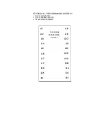
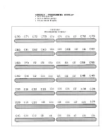
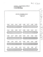
Page 33: ...ne 80 column SMDR line 8 Two 40 column SMDK lines RECALL Tape baud rate of 100 SAVE Tape baud rate of 50 7051684 master default CAUTION resets all values and clears all stored meinory Do not perform while system is in use 4 Press MONITOR PRXAMMING OVERLAYS Several different telephone and console overlays are packed with the system The overlay to be used is dependent upon the particular models of e...

Page 34: ...LAY 703804 275 OVERLAY 703500566 OVERLAV 7 0 3 5 0 0 4 6 7 0 b 00 OO 00 00 OO 00 00 El3 00 00 00 00 OO 00 00 0000000000 0000000000 0000000000 0000000000 t 6 300 0000000000 J F i g u r e 3 l Programming Overlay Identification ...

Page 35: ...se intercom first signalling l Press RECALL for voice l press SAVE for tone l Press 7 Specify central message desk one per system allowed 0 Press l Press keypad keys 010 041 to choose port 10 41 l Press 5b Set line length of printout l Press program key C38 l ress for one 80 col or 0 Press 8 for two 40 col 0 Press 8 Set recall time for unanswered call transfer l Press program key C33 0 Press keypa...

Page 36: ...console port Clil console port 10a Cl1 console port lla 0 Press console program key to specify console type Cl0 70 Key console Cl4 40 Key console Cl5 32 Key console l Repeat port and console selection steps for all required ports 11 Select baud rate of tape data 12 Press 0 Press program key C38 l Press RECALL for 100 baud 13 Press FIONITOK to exit or l Press SAVE for 5il baud proceed to next COS l...

Page 37: ...system being programmed 21 c34 RECALL FLASH TIME 5A 4 r I HOLD RECALL TIME KEY 1 TIME 1 ENTRY Note 0 program selection disa bled enables exclusive hold condi tion when set at station to place line on hold that cannot be released at any other station 6 INTERCOM FIRST CHOICE SIGNALLING w CENTRAL MESSAGE DESK STATION PORT ASSIGNED 8 3 7 ...

Page 38: ...4 1 015 f15 016 718 017 11w 016 E Its 019 llas 120 l E 10 i9 SPECIFY CONSOLE TYPE FOR EACH CONSOLE PORT CHOOSE PORT CHOOSE CONSOLE TYPE g PORT 10a 70 KEY CONSOLE 8 PORT lla 40 KEY CONSOLE g 32 KEY CONSOLE 11 G3 BAUD RATE OF TAPE DATA K E Y 1 BAUDRATE ENTRY Change page 3188 3 8 ...

Page 39: ...citly denied Also system speed dial numbers will not be toll restricted unless specified by station COS programming l Example A Provide a simple and broad toll restriction format by creating a DENY table with two entries Entry 1 1 Entry 2 0 This format prevents all long distance and operator calls l Example B Prevent the dialing of all numbers within the 804 area code while allowing the dialing of...

Page 40: ... Select table entry l Press program key Al A4 7 I Jeat steps 5 and 6 until all numbers are programmed in table 9 Press 10 Press M3tJITOR to exit or proceed to next COS programming step T3LL RIZS I RIC ION PROGRAMMING KEFERENCE TABLES RESTRICTION TABLE 1 RESTRICTION TABLE 2 TYPE ALLOW DENY TYPE ALLOW DENY NTRY ENTRY NUMBER 16 MAXIMUM 112 3 6 19 10 11 12 13 14 15 16 I I I I I I I RESTRICTION TABLE 3...

Page 41: ... 6 7 16 10 11 12 13 14 15 116 NTRY ENTRY NUMBI TABLE ASSIGNMENT LINES STATIONS RESTRICTION TABLE 11 RESTRICTION TABLE 12 DENY I TYPE ALLOW DENY 1 TYPE ALLOW TABLE ASSIGNMENT LINES STATIONS I TABLE ASSIGNMENT LINES __ STATIONS I I RESTRICTION TABLE 14 I RESTRICTION TABLE 13 TYPE ALLOW DENY I TYPE ALLOW DENY I ENTRY NUMBER 16 MAXIMUM I 10 11 12 13 14 15 16 TABLE ASSIGNMENT LINES __ STATIONS 1 RESTRI...

Page 42: ...only l None key C41 l Gp 1 key C34 l Gp 2 key C35 0 Gp 3 key C36 l Gp 4 key C37 6 Select privacy mode Press program key l Private key C28 l Non private key C29 3 Select line type Press program key l Disabled key C38 l Auxiliary key C39 l CO PBX key C40 5 Select dialing mode Press program key l Pulse tone key C26 0 Tone only key C27 7 Assign toll tables Press program key s l Clear all key C3 l Assi...

Page 43: ...k off or enter the values chosen for the lines being programmed 3 4 5 6 7 EATURE iELECT INE SROUPS MULTIFUNC rlON SYS EMS ONLY dODE RIVACY tiODE rOLL RESTRICTION TABLE ASSIGNMENT ABANDONED HOLD TIMEOUT COlPSX NUMBERS AND STATION ASSIGNMENTS Power Fail Lines 1 2 3 and 4 A Lead Control Lines 13 14 15 and 16 3 13 ...

Page 44: ...toll restric 0 i3 Field keys Bl B8 lines 1 8 disabled 22 Line Feature Ke set 0 Voice announce block disable Aqield keys lib 22 0 Privacy status private l B Field keys lines 1 8 PROCEDURE 0 Perform all steps in sequence l Skip those steps not required 1 Press 1 7 4 6 2 Press program key C41 base level entry program entry Specify station to be programmed 4 and perform applicable steps l Press keypad...

Page 45: ...lears previous settings l Press program key s per chart in step 11 Select ringing assignments RINGING 0 Press console key Cl8 clears previous settings l Press program key s per chart in step 11 DELAYED RINGING l Press console key Cl9 clears previous settings l Press program key s per chart in step 11 15 Select automatic privacy release 16 Select access denied 0 Press console key C21 l Press consol...

Page 46: ...rved link 0 Press console key Cl8 to continue with next step 21 sal call and or zone paging l Press RECALL to disable all paging assignments if desired ALL CALL 0 Press program key A4 to originate l Press program key A8 to receive 0 Press console key Cl8 to continue with next program step ZONES A B AND C l Press l Press program keys Al A3 and AS A7 to enable zones ORIGINATE RECEIVE KEY AllA2iA3 AS...

Page 47: ...l keys requiring line appearance Disable Line Appearance At Keys clears any prior assignment l Press key to be denied appearance Fast tone bursts sound l Press RECALL key tone bursts stop 0 Repeat procedure for all required key locations Assign DSS To Keys l Press key G be assigned A or B field Fast tone bursts sound l Press keypad keys 010 041 to choose station ports 10 41 Tone bursts stop l Repe...

Page 48: ...ed station l Press BOLD Press keypad keys to specify model station 0 Press keypad keys to specify first station in block l Press keypad keys to specify last station in block Note Flexible key function assignments for station port 10 or 11 cannot be changed by block programming 25 If block programming of step 24b is not performed repeat steps 5 through 24a for each station in system 26 Press MONITO...

Page 49: ...S PROGRAMMING REFERENCE TABLE Copy This Page To Provide Additional Reference l Shading denoteslinedefaultconditions Check caff or enter the values chosen for the fines being programmed BASELEVEL g STATION PROGRAMMING MODE 0 Sheets 15 18 ...

Page 50: ... one line call records may be lost 1 Press ITCM 7 4 6 base level entry if not active 2 Press program key C39 3 Choose desired printout 0 Press program key per chart PRIlJ I OUT All COS System COS Line C3S Toll Tables All station COS One Station COS PKOGRAM KEY c37 c3t c39 C4U c41 c34 plus 010 041 to choose station port 4 COS printout begins immediately 0 To abort printout press program key Crlc S ...

Page 51: ...LINE PRINTOUT FORMAT CARRIAGE RETURN AND LINE FEED CHARACTERS AT END OF LINE 1 ARE REPLACED BY TWO SPACES FOLLOWED BY ENTIRE CONTENTS OF LINE 2 OUTGOING CALL MUST BE OFF HOOK FOR 20 SECONDS MINIMUM OR NO RECORDING OCCURS PRINTOUT EXAMPLES 1 UNANSWERED INCOMING CALL 1 12 05 86 1651 NOANS 0 6 ANSWERED INCOMING CALL 1 6 1 12 05 86 16 52 1 6 0 2 ANSWERED INCOMING CALL 2 4 1 12 05 86 16 53 1 2 0 2 WITH...

Page 52: ... prepare recorder for recording 2 Cause recorder to begin recording blank cassette tape from beginning 3 Press ITCM 7 4 6 ITCM 4 Press appropriate program key to start recording process l c37 COS FEATURES l c34 ALL SPEED DIALS l c35 AUTODIALS STA 010 025 l C36 AUTODIALS STA 026 041 5 To abort procedure if required l Press ITCM 7 4 6 ITCM l Press program key C41 COS recording requires approximately...

Page 53: ...APE DATA ERROR LOADING COS DATA FROM TAPE To load previously recorded COS program values into system to replace current program values proceed as follows 1 2 3 4 5 Install pre recorded cassette tape and prepare recorder for playback Press ITCM 7 4 6 ITCM To load COS features l Press HOLD or To load memory dialing numbers 0 Press RECALL Start tape playback To abort the procedure if required l Press...

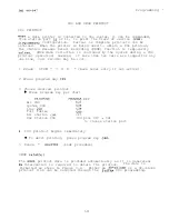
Page 54: ...ting will occur 5 To obtain a printing of the current clock date press ITCM Printing will occur automatically once each 24 hour period MO DY YR 0O OO current date and 0O OO hours POWER INTERRUPTION The system clock will continue to run for at least 30 minutes after AC power has been removed from the system If power is restored within the 30 minute backup period the following printing sequence will...

Page 55: ...nly 0 Dial 1 4 for group or Press a line key for line Note Key to line assignment per programming arrangement Refer to station COS programming reference chart for station port 10 key to line assignments or l Dial 0 for no group or line preselection 0 Dial speed dial number up to 32 digits eDia1 l 0 and l Press HOLD to store pause if required l Press RECALL to store flash if required Press SAVE and...

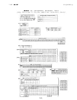
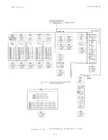
Page 56: ...UNCE g LcD SINGLE LlNElHOTELl 3 a L I N E 222 L I N E S I N G L E LINEIAGMINJ 0 0 0 F O R E X T N O ilOO I B A U D R A T E TOLL TABLES c SPEClFY C O N S O L E T Y P E F O R E A C H C O N S O L E P O R T S P E C I F Y C O N S O L E P O R T S P E C I F Y C O N S O L E T Y P E Figure 3 3a Programming Reference Chart 3 26 ...

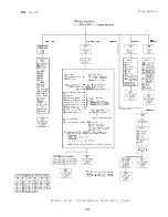
Page 57: ...RIG DENIED IDLE L I N E PREF 0 ASS I GN TOLL TABLES I TABLES l 16 ORESERVE ITCM L I N K Q Q SELECT LINKS I 7 or Jf NO RESERVED LINK I TO CONTINUE 0 ALL CALL ZONE PAGING E P CLEARS ALL a ALL CALL ORIG Q ALL CALL REC a a ZONES I 3 ORIG a a ZONES I 3 REC KEY MAPPING MODE 1DEPENOENT UPON PHONE TYPEI PRESS KEY TO BE DEFINED THEN PRESS FUNCTION LINES I 2 2 0 0 O P O R T ID DSS LF B BLANK AuT AL YNAMIc l...

Page 58: ...Y l Cut out along border l Cut out shaded openings l Fit over station faceplate Al Al A 2 A 2 A 3 A 3 A 4 A 4 A5 A5 A 6 A 7 IA 6 A 7 EXECUTECH A 8 PROGRAMMING A 9 OVERLAY 703804 274 A10 A l l A l 2 A l 3 A l 4 84 B5 B 6 87 Bl 82 83 ...

Page 59: ...OGRAMMING OVERLAY l Cut out along border l Cut out shaded openings l Fit over station faceplate Al A 2 A 3 A 4 A 5 A 6 A 7 0 7 B 5 83 I31 703500 566 PROGRAMMING A 8 A 9 OVERLAY AI0 All A l 2 A l 3 A l 4 88 B 6 84 82 ...

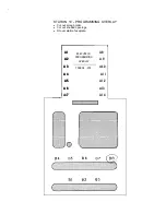
Page 60: ...3500 567 PROGRAMMING OVERLAY C70 C7l C72 c73 C74 C75 C76 C77 C78 c79 C60 C6l C62 C63 C64 C65 C66 C67 C68 c69 C50 C5l C52 C53 C54 C55 C56 C57 C58 c59 C40 C4l C42 C43 C44 C45 C46 C47 C48 c g c30 c31 C32 c33 C34 C35 C36 C37 C38 c39 c20 C2l C22 C23 C24 C25 C26 C27 C28 29 Cl0 CII C l 2 Cl3 cl4 Cl5 Cl6 cl7 Cl8 Cl9 ...

Page 61: ......

Page 62: ...If your KSU or an individual station needs repair subsequent to the warranty period it may be returned to Comdial Comdial will at their option either repair the defective equipment or replace it with a remanufactured unit This repair will be done for a fixed charge For information on this charge please call or write to the address given below Comdial 1180 Seminole Trail P 0 Box 7266 Charlottesvill...

Page 63: ... thesesLEDs are on they indicate that their corresponding power supply voltages are operational check out procedure for instructions for for possible failure A red LED located near the cassette music port is the system status indicator This indicator is turned on steady when power is applied to the KSU If the indicator flashes after power up it could be indicating a processor failure Unplug and re...

Page 64: ...CE INDICATION 1 B Field indiactors light in turn and stay on 2 ITCM indicator lights 3 MONITOR indicator lights 4 All indicators extinguish in same order as lighted 5 Ringer sounds be sure volume is set to med or high 22 LINE FEATURE KEYSET SEQUENCE INDICATION 1 MONITOR indicator lights 2 B Field indicators light in turn and stay on 3 HOLD indicator lights 4 ITCM indicator lights 5 A Field indicat...

Page 65: ...e indicators will then turn off and the console will become operational Paired Stations Station ports 10 through 41 are paired for data and for overload protection as shown below Console ports 10a and lla are not paired with any other port DATA PAIRING OVERLOAD PAIRING 10 11 CON 10a 12 13 CON lla 14 15 16 17 18 19 20 21 22 23 24 25 26 27 28 29 30 31 32 33 34 35 36 37 38 39 40 41 10 12 11 13 14 16 ...

Page 66: ...econnect them one at a time to isolate the faulty one Failure Analysis ___ KSU And Station Figure 4 2 details a failure analysis flow chart to assist a service technician in isolating a failure in a defective system One way to isolate a failure is to substitute a known good assembly for a suspected one This is the recommended failure isolation method to use with the system Connecting and disconnec...

Page 67: ...lAtl3S 3AVH IN wN ISSV 3Nll SO3 WVkJOOtrd3 nSll NO ItlOd 3Nil xad 03i31a3snNn 013Nl l a3llVJtlOj 1ndNl XBd 03131133NN03 3sm 3lVlHdOMddV HllM 3Snj N3dO 33Vld3tl S3h A DNIXL1OM nSX 01 1CldNl 3Nll X8d1031319NION0dS3 03 133NN03Sl l IlSu WOkI 3Nll amw31vlosI NO 03t1ois3tl 33lAt43S 3AWH ...

Page 68: ...holes as illustrated in Figure 4 3 4 Replace the lower housing Make sure that all wires are clear Wall Mounting Mount the station directly on the wall using two lo panhead screws obtained locally or mount it on a wall jack cover plate 1 2 Thread the lo screws into the wall within l 8 inch of the surface Refer to Figure 4 3 for the spacing dimensions Insure that the housing is converted properly fo...

Page 69: ...tory I And Discard When Wall z J Mounting The Telephone K Places For lO Screws 3 Place for Latching Lever Push In To Latch Pull Out To Unlatch Housing Screws 4 Places Fic ure 4 3 Station Wall Mounting Details Note 22 Line Feature Keyset shown Single Line Keyset similar ...

Page 70: ...x14 Key Field Speakerphone 10x14 Key Field LCD Display Monitor 10x14 Key Field Data Jack Speakerphone 10x14 Key Field Data Jack Speakerphone 10x14 Key Field Data Jack LCD Monitor 5x20 Key Field Data Jack Speakerphone 5x20 Key Field Data Jack Monitor 2x22 Key Field Speakerphone 2x22 Key Field Monitor 2x22 Key Field Speakerphone 2x22 Key Field Single Line Keyset Proprietary Desk Wall Message Waiting...

Page 71: ......

Page 72: ...LF CONSOLE 2 4 CONNECTIONS LINE 2 3 CONNECTIONS POWER FAILURE STATIONS 2 4 CONNECTIONS STATION AUXILIARY JACK 2 4 CONNECTIONS STATION 2 3 CONVERSION DESK VJALL OF STATIONS 4 5 COS PRINTOUT 3 20 DATA DEVICE CONNECTIONS 2 5 DEFAULT CLASS OF SERVICE 3 3 DEFAULTS LIIJE 3 12 DEFAULTS STATION 3 14 DEE AULTS SYSTEM 3 5 DESK WALL REVERSAL AND WALL MOUNTING OF STATIONS 4 5 DSS BLF CONSOLE CONNECTIONS 2 4 D...

Page 73: ...LEPHONE COMPANY l 2 PAIRED STATIONS 4 4 PARTY LINES AND COIN LINES l 3 POUER FAILURE STATION CONNECTIONS 2 4 PRINTOUT COS AND SMDR DATA 3 20 PROCEDURE LINE COS PROGRAMMING 3 12 PROCEDURE SYSTEM COS PROGRAMMING 3 5 PROGAMMING OVERLAYS 3 3 PROGRAMMING PROCEDURE SYSTEM COS 3 5 PROGRAMMING LINE COS 3 12 PROGRAMMING STATION COS 3 14 PROGRAMMING SYSTEM SPEED DIAL 3 25 PROGRAMMING SYSTEM 3 l PROGRAMMING ...

Page 74: ...TEM MUTIFUNCTION SYSTEM CHECKOUT 2 2 SYSTEM CLOCK INFORMATION 3 24 SYSTEM COS PROGRAMMING PROCEDURE 3 5 SYSTEM COS PROGRAMMING REFERENCE TABLE 3 5 SYSTEM DEFAULTS 3 5 SYSTEM GROUNDING 2 6 SYSTEM PROGRAMMING 3 1 SYSTEM SPEED DIAL PROGRAMMING 3 25 SYSTEM STATUS INDICATORS 4 3 SYSTEM WIRING 2 3 TABLE ENTRY PROCEDURE TOLL RESTRICTION 3 7 TABLE OF CONTENTS l v TECHNICAL ASSISTANCE AND REPAIR SERVICE 4 ...

Page 75: ......

Page 76: ...stallation Other Cl Training 0 Maintenance Please check specific criticism s give page number s and explain below 0 Clarification on page s Cl Error on page s 0 Addition on page s 0 Deletion on page s I Thank you for your cooperation If a reply is required please check 0 Name Your Function Company Address City State Date Zip ...

Page 77: ...NESS REPLY MAIL FIRST CLASS MAIL PERMIT NO 594 CHARLOITESVILLE VA 22906 POSTAGE WILL BE PAID BY ADDRESSEE COMDIAL TECHNICAL PUBLICATIONS DEPARTMENT P 0 BOX 7266 CHARLOTTESVILLE VA 22906 7266 I l l l ll l ll l l ll 1ll l l ll l l l I I I f I f t I I I I _ _ F o l d i I I I Please Tape Do Not Staple ...

Page 78: ...OREGOING WARRANTY THE MAXIMUM LIABILITY OF COMDIAL UNDER ANY WARRANTY STATUTORY EXPRESS OR IMPLIED IS LIMITED TO THE PURCHASE PRICE OF THE EQUIPMENT COMDIAL SHALL HAVE NO RESPONSIBILITY FOR DAMAGE TO PROPERTY OR ANY OTHER LOSS OR INJURY INCLUDING CONSEQUENTlALANDlOR INCIDENTAL DAMAGES RESULTING FROM THE POSSESSION OPERATION OR USE OF THE EQUIPMENT ALL SUCH CLAIMS BEING HEREBY EXPRESSLY WAIVED THE ...

Page 79: ...COMDIAL Charlottesville Va 22901 PRINTED IN U S A 716604 700 01 ...

Page 80: ......

Reviews: