background image

                                           INSTRUCTIONS FOR TECHNICAL PERSONNEL

33

ENERGY CONSUMPTION

Mod.

Tank
capacity
(l)

Water
consumption
per cycle (l)

Tank
heater (W)

booster
heater (W)

Pump
(W)

Total
power
(W)

Max hourly
production
racks with
inlet water
at 55°C

Max hourly
production
racks with
inlet water at
12°C

FC54-E

15

3.5

2000

3000

450

3450

30/20

10

FC54-EA

15

3.5

2000

3000

450

3450

30/20

10

In the event of low water supply temperature, the will be a subsequent
machine output drop.

Summary of Contents for FC54-E

Page 1: ...18 MANUALE DI ISTRUZIONE PER LAVASTOVIGLIE INSTRUCTION MANUAL FOR DISHWASHERS NOTICE D UTILISATION POUR LAVE VAISSELLE GEBRAUCHSANWEISUNG FÜR GESCHIRRSPÜLER ...

Page 2: ...d be destined to the use which it has been conceived for Any other application should be considered improper and consequently dangerous 6 The equipment should only be used by personnel trained for its use 7 Operators must strictly follow all hygienic requirements in the handling of clean dishware and cutlery 8 Do not leave the machine in an environment at temperatures lower than 0 C 9 The protecti...

Page 3: ...19 INSTRUCTIONS FOR USE ...

Page 4: ...p H1 H2 flashes 3 As soon as lamp H1 H2 is on pour about 30 gr of detergent directly into the tank paying attention to distribute it uniformly on the filters anyway the quantity being according to supplier s instructions Add 15 gr every 7 cycles to achieve a concentration of 1 5 gr lt In order to respect our environment use only the correct amount of detergent When using chlorinated detergent it i...

Page 5: ...uto cycle intervenes and the cycle is pro longed flashes the H3 indicator to indicate this intervention In any case after 8 minutes max the intervention is stopped and the cycle continues 6 Remove the rack and slightly incline it to permit a perfect drain allow dishware to dry and after having washed one s hands handle the rack in order not to touch the dishware inside then place the rack on hygie...

Page 6: ...hrough the general wall switch and close the water supply INSTRUCTIONS DURING THE WASHING 1 Do not plunge bare hands into the water containing the detergent If this happens wash them immediately and abundantly with fresh water 2 When the machine is operating do not open the door too rapidly 3 Use only specific anti foaming detergents 4 Disconnect the equipment in case the machine is out of order o...

Page 7: ...um salt in the water can compromise machine performance thus ask qualified personnel to remove the deposits periodically In order to avoid some oxidation risks or chemical reactions generally the stainless steel surfaces have to be well cleaned 2 OPTIMAL RESULTS A possible wash deficiency can be noticed when residue remains Marks can be caused by an insufficient rinse in this case check that the r...

Page 8: ...d the electric pump 4 SANITIZING THE MACHINE Sanitizing the machine at least once a week is of the utmost importance in order to guarantee hygiene even when the machine is not in use It is advisable to use a disinfecting product suggested by an authorised detergent dealer The use of this product will satisfy hygienic requirements even during machine non use Before switching off the machine run the...

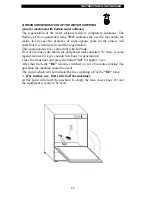
Page 9: ...ration This operation has to be carried out with full tank First of all make sure that in the designated tank container S there is some regeneration salt 1kg is enough for about 5 regenerations Close the front door and press the button S4 for approx 3sec After that the lamp H4 remains switched on for 20 minutes during this operation the machine cannot be used The end of which will be indicated by ...

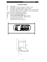
Page 10: ...utton SELF CLEANING DRAIN CYCLE machine OFF Push button DRAIN CYCLE machine ON door frontal opened H1 H2 Pilot lamp MACHINE ON flashing H1 H2 Pilot lamp MACHINE READY fixed H3 Pilot lamp MACHINE WORKING H4 Pilot lamp REGENERATION mod FC54 EA H5 Pilot lamp SELF CLEANING DRAIN CYCLE S Salt container mod FC54 EA I Regulating screw for rinse aid injector ...

Page 11: ... addressed to a qualified personnel the only one authorised to carry out checks and repairs if any The manufacturer declines any responsibility in the case of interventions made by a non qualified personnel or the use of spare parts other than those supplied by the Manufacture ...

Page 12: ... not efficient there will be a dispersion due to the suppresser The machine shall be included in a correctly dimensioned equipotential whose effectiveness is to be very tight in accordance to the procedures set for in the applicable safety standards The connection shall be performed through a screw marked by a plate near the rear side of the appliance The manufacturer declines any responsibility f...

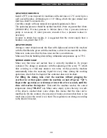
Page 13: ...have constrictions Make sure that the building drain tubing withstands temperatures up to 70 C 5 RINSE AID DOSAGE Make sure that rinse aid suction hose is correctly installed in it s proper container The dosage is automatic with the adjusting of the screw I which after screwing to a full stop unscrew two turns At this point the machine automatically takes the necessary liquid for every rinse durin...

Page 14: ...n the screw until the desired intake quantity has been reached The correct quantity is indicated by the detergent supplier Check that the intake of the pipe during the rinse cycle is as preset 1cm 1g approximately Maximum intake or delivery distance 2 meters To see the image for the detergent immission hole in the tank To see the electrical diagram enclosed for the electrical connection cables nr ...

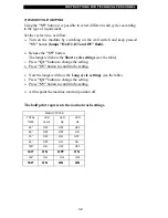
Page 15: ...s will show the Short cycle settings see the table C Press Q1 button to change the setting D Press S5 button to confirm the setting E Now the lamps will show the Long cycle settings see the table F Press Q1 button to change the setting G Press S5 button to confirm the setting H At this point the machine return in position off The bold print represents the normal wash settings WASH CYCLES TOTAL TIM...

Page 16: ... W booster heater W Pump W Total power W Max hourly production racks with inlet water at 55 C Max hourly production racks with inlet water at 12 C FC54 E 15 3 5 2000 3000 450 3450 30 20 10 FC54 EA 15 3 5 2000 3000 450 3450 30 20 10 In the event of low water supply temperature the will be a subsequent machine output drop ...

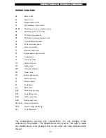
Page 17: ...Regeneration solenoid valve C3 Condensator C1 Anti noise filter X1 Terminal board M3 Wash pump MD Detergent dispenser M5 Drain pump M2 Rinse boiler pump S2 Pressure switch E2 Booster heater E3 Tank heater K1 Main relay KH2 Machine ready relay KS2 Tank filling relay KM3 Wash pump relay KM2 Rinse pump relay SE2 SE2a Booster thermostat SE2b Booster safety thermostat SE3 Tank thermostat The manufactur...

Page 18: ...05 2001 CODICE 900173 ...

Reviews: