USER MANUAL FOR MBDA-200S
ENU STATUS : 1-0-0
Copyright - refer to title page
Page 27
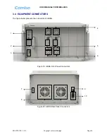
Table 3: mBDA Connections
Identifier
Functional Description
1. OMT/LAN/RS485
OMT port is for local commissioning; LAN port is for remote
connection; RS485 is for extension connection when adding extended
equipment.
2. LED indicator
LED indicator. Refer to Table 5 for the detailed information.
3.EXT_ALM
External alarm connector with 4 pins. Refer to Table 4 for the detailed
information.
4.DT
RF input port, Mini Din female
5.CPL
Output coupler port, -40dB, QMA female
6.MT
RF output port, Mini Din female
7.
Grounding connector.
8. FAN
Fan inside
9. POWER
Power switch.
10. AC100~240V
AC power supply connector.
3.5 EQUIPMENT CONNECTION
3.5.1 GROUNDING CONNECTION
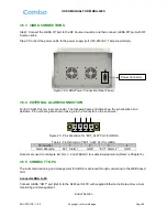
3.5.2 mBDA GROUNDING CONNECTION
Step 1: Connect the GND cable to the GND connector and the building EARTH. Recommended GND
cable size is # 12 AWG.
Step 2: Ensure the GND cable is connected to building GND.
Figure 21: mBDA Grounding (mBDA Rear Panel)
WARNING!
This unit must always be grounded. Consult an appropriate electrical
inspection authority or an electrician if you are uncertain that suitable
grounding is available.
Do not connect power before grounding.
Grouding Connector

