background image

11

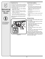
5

Maintaining 

Your Lawn 

Mower

An unbalanced blade 
will cause excessive 
vibration when rotat-
ing at high speeds. It 
may cause damage 
to mower, and could 
break causing per-
sonal injury.

When removing 
the cutting blade 
for sharpening or 
replacement or 
when sliding the belt 
around it, protect 
your hands with a 
pair of heavy gloves 
or use a heavy rag to 
hold the blade.

WARNING

Figure 5-5

AdjustmentsVariable Speed Cable

Periodic adjustment of the variable speed cable may 
be necessary due to normal wear on the drive system. 
Adjustment is needed if unit begins to run too slow or too 
fast.
1.  Start engine and place shift lever in the third speed 

position.

2.  Stop engine and disconnect spark plug wire and 

ground it against engine.

3.  With engine off, shift back to first speed. This will 

provide slack in the cable.

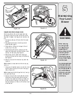
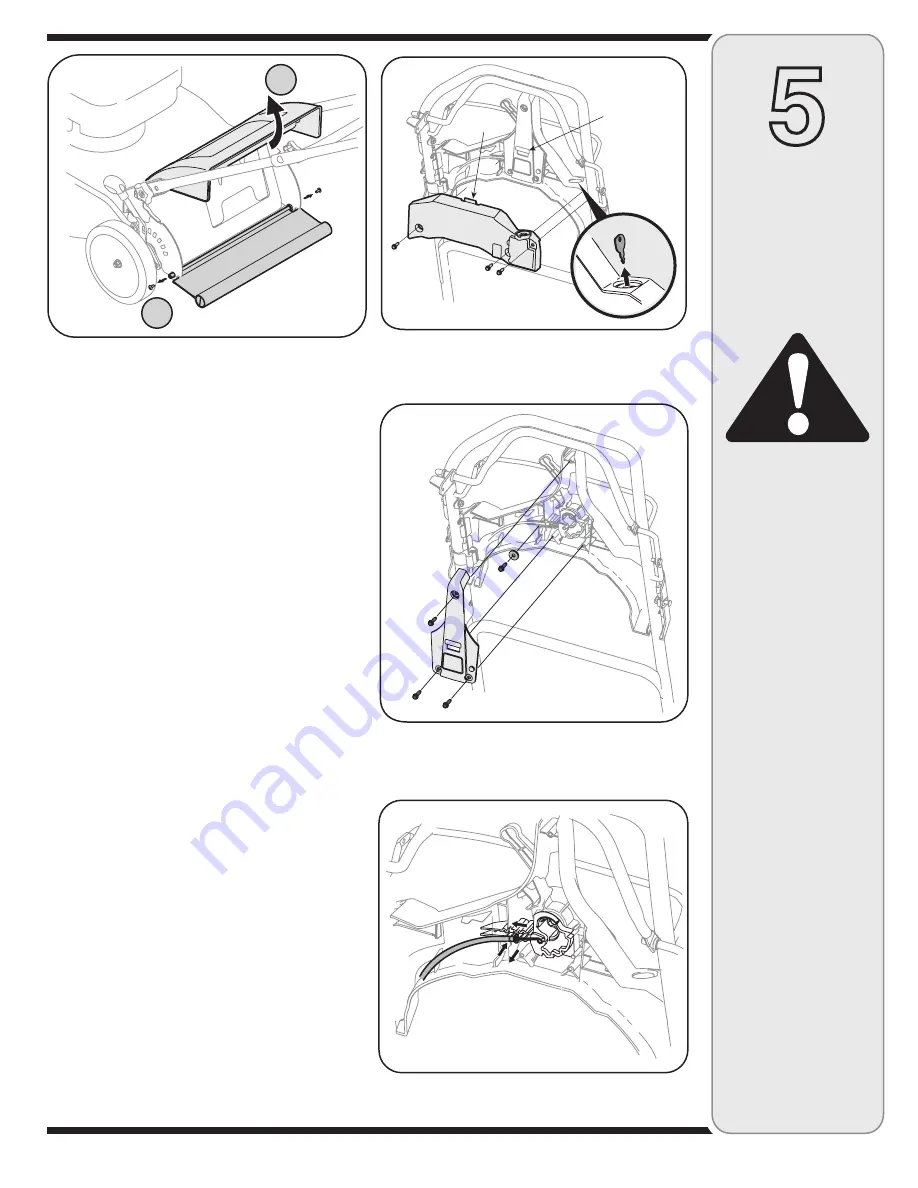
4.  Carefully remove the harness assembly from the 

speed control housing by removing the three screws 
securing it to the housing. See Figure 5-3.

5.  Remove back cover of speed control housing by 

removing the three screws securing it to the housing. 
See Figure 5-4.

6.  Remove screw and flat washer securing cable. See 

Figure 5-4. 

NOTE: 

Make sure to take note of which slot in housing 

cable is in.
7.  Using a pair of needle nose pliers or similar tool, move 

eyelet in cable only one slot to the left in housing as 
shown in Figure 5-5.

NOTE: 

Moving eyelet to the left speeds unit up; moving it 

to the right slows it down.
8.  Replace screw and washer removed earlier and reas-

semble back of housing. Reattach battery harness 
assembly to the speed control housing, making sure 
to snap the tab on the harness into the slot on the 
housing. See Figure 5-3. Secure with the three screws 
removed earlier.

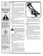
B

A

Figure 5-2

Figure 5-4

Tab

Slot

Figure 5-3

Summary of Contents for J830 Series

Page 1: ...TIONS CAREFULLY BEFORE OPERATING EQUIPMENT Safety Setup Adjustments Operation Maintenance Troubleshooting Parts Lists Warranty LES DISTRIBUTIONS RVI LIMITÉE 2955 JEAN BAPTISTE DESCHAMPS LACHINE QUEBEC H8T 1C5 21 Self Propelled Rotary Mower Model Series J830 02 08 08 769 03848 ...

Page 2: ...assembling this product or have any questions regarding the controls operation or maintenance of this unit please call an authorized dealer Please have your unit s model number and serial number ready when you call See previous section to locate this information 2 The engine manufacturer is responsible for all engine related issues in terms of performance power rating specifications warranty and s...

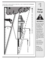
Page 3: ... and you could slip resulting in serious injury Operate RIDING mowers up and down slopes never across the face of slopes Operate WALK BEHIND mowers across the face of slopes never up and down slopes Sight and hold this level with a vertical tree or a corner of a building or a fence post F o l d a l o n g d o t t e d l i n e r e p r e s e n t s a 1 5 s l o p e 15 Use this page as a guide to determi...

Page 4: ...nd automatically return to the disengaged position when released 18 Never operate the mower in wet grass Always be sure of your footing A slip and fall can cause serious personal injury If you feel you are losing your footing release the blade control handle immediately and the blade will stop rotating within three seconds 19 Mow only in daylight or in good artificial light Walk never run 20 Stop ...

Page 5: ...odorless and deadly gas 2 Before cleaning repairing or inspecting make certain the blade and all moving parts have stopped Disconnect the spark plug wire and ground against the engine to prevent unintended starting 3 Check the blade and engine mounting bolts at frequent intervals for proper tightness Also visually inspect blade for damage e g bent cracked worn Replace blade with the original equip...

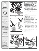
Page 6: ...s See Figure 3 2 3 Rope guide Setup as follows see Figure 3 3 a Hold the blade control against the upper handle Position A b Slowly pull starter rope out of engine Position B Release blade control c Slip starter rope into the rope guide Position C d Tighten rope guide wing nut Position D 4 Secure cables to the lower handle using the cable tie Pull cable tie tight and cut off excess 5 To assemble t...

Page 7: ...n the pivot rod and the rear discharge door rests firmly against top of the grass catcher 8 To install the rear mulching plug a Lift rear discharge door and lift grass catcher up and out off of the pivot rod b Insert the rear mulching plug as shown in Figure 3 4 and release the rear discharge door 9 If converting to side discharge make sure grass catcher is off unit and rear mulching plug is in pl...

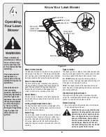
Page 8: ...ed of the mower See Figure 4 1 inset IMPORTANT Move the speed control only when the engine is running Changing the speed control setting with the engine off can damage the mower NOTE The speeds noted on the speed control are not exact Speed will vary depending on belt wear cable wear and mowing conditions Electric Start Ignition Switch The electric start ignition switch is located on the right sid...

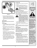
Page 9: ...top Engine 1 Release the blade control handle to stop the engine and blade 2 Disconnect and ground the spark plug wire as instructed in the separate engine manual to prevent accidental starting while equipment is unattended WARNING Wait for the blade to stop completely before doing any work on the mower or to remove the grass catcher Using Your Lawn Mower Be sure the lawn is clear of stones sticks...

Page 10: ... deck with a suitable tool Do not spray with water IMPORTANT Do not use a pressure washer or garden hose to clean your unit These may cause damage to bearings or the engine The use of water will result in shortened life and reduce serviceability 4 Put the mower back on its wheels on the ground If you had put plastic under the gas cap earlier make sure to remove it now Engine 1 Refer to the separat...

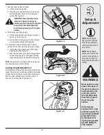
Page 11: ...t speed This will provide slack in the cable 4 Carefully remove the harness assembly from the speed control housing by removing the three screws securing it to the housing See Figure 5 3 5 Remove back cover of speed control housing by removing the three screws securing it to the housing See Figure 5 4 6 Remove screw and flat washer securing cable See Figure 5 4 NOTE Make sure to take note of which...

Page 12: ...nbalance condition is not the responsibility of the manufacturer NOTE Always remove blade from the adapter for testing balance 5 The blade can be tested for balance by balancing it on a round shaft screwdriver Remove metal from the heavy side until it balances evenly 6 Before reassembling the blade and the blade adapter to the unit lubricate the engine crankshaft and the inner surface of the blade...

Page 13: ...moved earlier WARNING Do not remove the battery pack from the electric starter housing for any reason other than replacement Figure 5 7 Figure 5 8 Charging Battery WARNING The battery contains corrosive fluid and toxic material handle with care and keep away from children Do not puncture disas semble mutilate or incinerate the battery Explosive gases could be vented during charging or discharg ing...

Page 14: ... warranty operator must maintain the lawn mower as instructed here 3 Changing of engine governed speed will void engine warranty 4 All adjustments should be checked at least once each season 5 Periodically check all fasteners and make sure these are tight Off Season Storage The following steps should be taken to prepare your lawn mower for storage Clean and lubricate mower thoroughly as described ...

Page 15: ... Engine overheats 1 Fill crankcase with proper oil 2 Refer to the engine manual packed with your unit 3 Remove blower housing and clean 4 Refer to engine manual 1 Engine oil level low 2 Dirty air filter 3 Air flow restricted 4 Carburetor not adjusted properly Occasional skip hesitates at high speed 1 Adjust gap to 030 Refer to engine manual 2 Refer to engine manual 1 Spark plug gap too close 2 Car...

Reviews: