background image

10

S

ection

 3 — A

SSembly

 & S

et

-U

p

Attaching the Grass Catcher 

(If Equipped)

1. 

Follow steps below to assemble the grass catcher. Make 

certain bag is turned right side out before assembling 

(warning label will be on the outside).

a.  Place bag over frame so that its black plastic side is 

at the bottom.

b.  Slip plastic channel of grass bag over hooks on the 

frame. See Figure 3-4.

Figure 3-4

2. 

Follow steps below to attach grass catcher:

a.  Push down on the handle adjustment lever and 

pivot handle into storage position. 

See Figure 3-5.

Figure 3-5

b.  Open the rear discharge door using the door handle. 

See Figure 3-6.

Handle

Figure 3-6

c.  Place the grass catcher into the slots on the rear 

discharge support bracket. See Figure 3-7 inset.

Figure 3-7

d.  Pivot the grass catcher down so that it rests over the 

rear opening of the mower. See Figure 3-8. Let go 

of discharge door so that it rests against the grass 

catcher.

To remove grass catcher, hold open rear discharge door on the 

mower. Lift grass catcher up and off of the slots in the handle 

brackets. Release rear discharge door to allow it to close rear 

opening of mower.

Summary of Contents for 12ABW32G897

Page 1: ...ULES AND INSTRUCTIONS IN THIS MANUAL BEFORE ATTEMPTING TO OPERATE THIS MACHINE FAILURE TO COMPLY WITH THESE INSTRUCTIONS MAY RESULT IN PERSONAL INJURY OPERATOR S MANUAL MTD PRODUCTS LIMITED 97 KENT AVENUE KITCHENER ONTARIO N2G 4J1 MTD LLC P O BOX 361131 CLEVELAND OHIO 44136 0019 769 11360 12 17 15 28 Rear Wheel Drive Self Propelled Mower ...

Page 2: ... Please read this entire manual prior to operating the equipment It instructs you how to safely and easily set up operate and maintain your machine Please be sure that you and any other persons who will operate the machine carefully follow the recommended safety practices at all times Failure to do so could result in personal injury or property damage All information in this manual is relative to ...

Page 3: ...anders helpers and pets at least 75 feet from mower while it is in operation Stop machine if anyone enters area 9 Always wear safety glasses or safety goggles during operation and while performing an adjustment or repair to protect your eyes Thrown objects which ricochet can cause serious injury to the eyes 10 Wear sturdy rough soled work shoes and close fitting slacks and shirts Shirts and pants ...

Page 4: ...s made for this machine by the manufacturer Failure to do so can result in personal injury 27 When starting engine pull cord slowly until resistance is felt then pull rapidly Rapid retraction of starter cord kickback will pull hand and arm toward engine faster than you can let go Broken bones fractures bruises or sprains could result 28 If situations occur which are not covered in this manual use ...

Page 5: ...equipped to prevent unintended starting 3 Check the blade and engine mounting bolts at frequent intervals for proper tightness Also visually inspect blade for damage e g bent cracked worn Replace blade with the original equipment manufacture s O E M blade only listed in this manual Use of parts which do not meet the original equipment specifications may lead to improper performance and compromise ...

Page 6: ...ndary Air Injection SAI and Three Way Catalyst TWC if so equipped Spark Arrestor WARNING This machine is equipped with an internal combustion engine and should not be used on or near any unimproved forest covered brush covered or grass covered land unless the engine s exhaust system is equipped with a spark arrester meeting applicable local or state laws if any If a spark arrester is used it shoul...

Page 7: ...njury keep hands and feet away Do not operate unless discharge cover or grass catcher is in its proper place If damaged replace immediately DANGER BYSTANDERS Do not mow when children or others are around DANGER HAND FOOT CUT Keep hands and feet away from rotating parts DANGER THROWN DEBRIS Remove objects that can be thrown by the blade in any direction Wear safety glasses DANGER SLOPES Use extra c...

Page 8: ...NE IF A SLOPE IS TOO STEEP FOR SAFE OPERATION To check the slope proceed as follows 1 Remove this page and fold along the dashed line 2 Locate a vertical object on or behind the slope e g a pole building fence tree etc 3 Align either side of the slope gauge with the object See Figure 1 and Figure 2 4 Adjust gauge up or down until the left corner touches the slope See Figure 1 and Figure 2 5 If the...

Page 9: ...ine or oil in the engine Fill up with gasoline and oil as instructed in the accompanying engine manual BEFORE operating your mower Handle Remove any packing material which may be between the handle and the mower 1 Tighten star knobs securing lower and upper handles together 2 Push down on the handle adjustment lever with your foot See Figure 3 1 Figure 3 1 3 Pivot the handle into operating positio...

Page 10: ...djustment lever and pivot handle into storage position See Figure 3 5 Figure 3 5 b Open the rear discharge door using the door handle See Figure 3 6 Handle Figure 3 6 c Place the grass catcher into the slots on the rear discharge support bracket See Figure 3 7 inset Figure 3 7 d Pivot the grass catcher down so that it rests over the rear opening of the mower See Figure 3 8 Let go of discharge door...

Page 11: ...g deck lift the mulch plug See Figure 3 10 3 Insert the top of the chute into the opening of the grass catcher support bracket See Figure 3 11a 4 Pivot the chute towards the mowing deck and over the opening in the side of the mowing deck See Figure 3 11b 5 Secure the chute to the mowing deck using the wing knob included in the manual bag Thread the wing knob onto the deck stud Hand tighten to secu...

Page 12: ...of six positions on each caster assembly Refer to Figure 3 16 a b Figure 3 16 Attaching Side Discharge Chute Your mower is shipped as a mulcher To convert to side discharge make sure grass catcher is off the unit and mower rear discharge door is closed 1 On the side of the mower deck lift the mulch plug See Figure 3 13 Deck Stud Mulch Plug Figure 3 13 2 Slide two hooks of side discharge chute unde...

Page 13: ... 1 Lift lock pins 2 Place in larger holes to lock wheels Place pins in smaller holes to allow casters to rotate freely for turning Set Up Gas and Oil Fill Up Refer to the separate engine owner s manual for additional engine information 1 Add oil provided before starting unit for the first time out of the box 2 Service the engine with gasoline as instructed in the separate engine owner s manual WAR...

Page 14: ...e mower Press down on it prior to engaging the blade control Blade Control The blade control is attached to the upper handle of the mower After pressing down on the lockout lever depress and squeeze it against the upper handle to engage the blade Release it to stop the blade WARNING The blade control is a safety device Never attempt to bypass its operations Figure 4 1 Lawn Mower controls and featu...

Page 15: ...urn the engine OFF Recoil Starter The recoil starter is located on the engine Pull the recoil starter rope to start the unit Starting Engine WARNING Be sure no one other than the operator is standing near the lawn mower while starting engine or operating mower Never run engine indoors or in enclosed poorly ventilated areas Engine exhaust contains carbon monoxide an odorless and deadly gas Keep han...

Page 16: ...l it will return to the neutral position and the drive will be disengaged NOTE For ease of use while gripping the controls simply lock your wrist and elbows and walk the unit will automatically adjust to your speed WARNING The operation of any lawn mower can result in foreign objects being thrown into the eyes which can damage your eyes severely Always wear safety glasses while operating the mower...

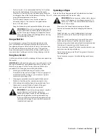
Page 17: ... in the Assembly Setup section on page 10 Grass clippings will automatically collect in bag as you run mower Operate mower until grass bag is full 2 Stop engine completely by releasing the blade control Make sure that the unit has come to a complete stop 3 Lift discharge door and pull grass bag up and away from the mower to remove the bag Dispose of the grass clippings and reinstall the bag when c...

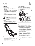
Page 18: ...el axles and casters is equipped with a grease fitting See Figure 4 3 Lubricate with a No 2 multi purpose grease applied with a grease gun after every 25 hours of mower operation or once a season Figure 5 2 Engine A list of key engine maintenance jobs required for good performance by the mower is given below Follow the accompanying engine manual for a detailed list and instructions Maintain oil le...

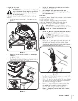
Page 19: ...3 Attach garden hose with the deck wash nozzle to the water port on your deck s surface See Figure 5 5 Figure 5 5 4 Turn the water ON and start the engine as described in the Controls Operation section 5 While in the operator s position behind the mower depress the lockout lever and pull the blade control back against the drive control to engage the blades 6 Remain in the operator s position with ...

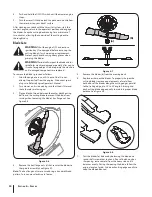
Page 20: ...ug wire Refer to Engine Operator s Manual 2 Turn mower on its side making sure that the air filter and the carburetor are facing up 3 Place a block of wood between the center deck housing baffle and the cutting blade to prevent the blade from turning when loosening the blade s hex flange nut See Figure 5 6 Figure 5 6 4 Remove the hex flange nuts a that secures the blades to the spindle assembly Se...

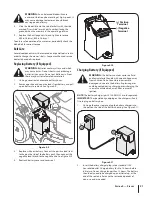
Page 21: ...ery to remove See Figure 5 9 Figure 5 9 3 Replace with new battery Connect the positive lead red to the positive side of the battery pack then connect the negative lead black to the negative side See Figure 5 10 4 Reattach battery cover and cover seal Positive Terminal Negative Terminal Figure 5 10 Charging Battery If Equipped WARNING The battery contains corrosive fluid and toxic material handle ...

Page 22: ...wer thoroughly as described in Lubrication section on page 18 Apply a coat of chassis grease to mower s cutting blades to prevent rusting Refer to Engine Operator s Manual for correct engine storage instructions Do not use a pressure washer to clean your unit Store mower in a dry clean area Do not store next to corrosive materials such as fertilizer When storing any type of power equipment in a po...

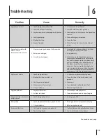
Page 23: ...e blade Carefully clean out debris if necessary Reattach spark plug boot and reinsert electric starter push key Wait one minute after tripping for circuit breaker to automatically self reset then reattempt start Engine runs erratic 1 Spark plug boot loose 2 Blocked fuel line or stale fuel 3 Vent in gas cap plugged 4 Water or dirt in fuel system 5 Dirty air cleaner 1 Connect and tighten spark plug ...

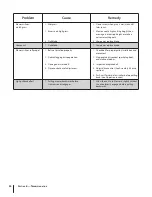
Page 24: ...f propel 1 Belt not installed properly 2 Debris clogging drive operation 3 Damaged or worn belt 4 Drive control out of adjustment 1 Check belt for proper pulley installation and movement 2 Stop engine disconnect spark plug boot and clean out debris 3 Inspect and replace belt 4 Adjust drive control See Assembly Set up section 5 Push unit forward a few inches before pulling back See Operation sectio...

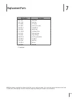
Page 25: ...ing locating your model and serial numbers Part Number Description 951 10292 Spark Plug 951 12296 Fuel Filter 931 04669 Air Cleaner 951 14407 Fuel Cap Assembly 634 05220 Front Wheel 634 05196 Rear Wheel 731 10510A Discharge Chute 942 05130 Mulching Blade 942 05235 High Lift Blade 664 05060 Grass Bag Columbia 954 05090 Drive Belt 954 05106 Deck Belt 725 04903 Battery 731 09728 Push Key If equipped ...

Page 26: ...b site at www mtdcanada com This limited warranty does not provide coverage in the following cases a The engine or component parts thereof These items may carry a separate manufacturer s warranty Refer to applicable manufacturer s warranty for terms and conditions The Powermore engine is not excluded under this agreement b Log splitter pumps valves and cylinders have a separate one year warranty c...

Page 27: ...E RESPECTIVE MANUFACTURERS SERVICE DEALERS Belts light bulbs clutch parts friction wheels grass bags tires seats rider deck wheels and cutting blades are covered by a 60 day limited warranty Batteries are warranted against defect for 90 days at 100 of their value and 50 of their value for the period between the 91st day and the 120th day Fuses shear bolts and blade adapters are considered consumab...

Page 28: ...28 Notes ...

Reviews: