background image

17 


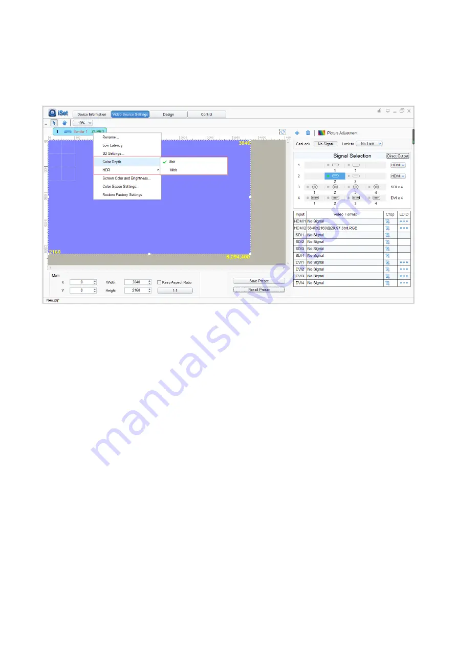
Color Depth 

The 

[Color Depth]

 output of 8 bit up to 4096x216 and 10 bit up to 3820x2160. 


Loop 

Use two H10FN to connect the Z6 PRO optical fiber output port 1 and 2. Make the port 

1 as the main output, and port 2 as reduentant output. Then, use network cables to connect 

start of cabinets form the first H10FN and end connect to the second H10FN. When the main 

output losts output signal, and the redundant one will work automatically, once the main signal 

working again and output will switch to the main one.       


Summary of Contents for Z6 PRO

Page 1: ...Z6 PRO Super Controller...

Page 2: ...3 Design 19 5 4 Control 23 6 LCD Operate Instruction 24 6 1 Operational Instruction 24 6 2 Starter 25 6 3 Main Interface 26 6 4 Operation Instruction 26 6 4 1 Display Setting 27 6 4 2 EDID Setting 30...

Page 3: ...wer cord into the power receptacle 1 3 Keep this product far away from magnets motors and transformers This product is an electronic product Contact of functional interface with charged objects may ca...

Page 4: ...o 4096 2160 60Hz resolution per board Support 3 types of optional 4k input boards including HDMI DP 4 DVI 4 SDI 4 10G optical fiber output ports loading capacity up to 8847360 pixels maximum width 819...

Page 5: ...5 3 Hardware The Front Panel The Back Panel...

Page 6: ...8 10bit support RGB444 YCbCr444 YCbCr422 YCbCr420 4096 2160 60Hz 8bit support RGB444 YCbCr444 YCbCr422 YCbCr420 2 4 DVI input board Input signal 4 x DVI inputs Standard VESA standard support HDCP comp...

Page 7: ...7 4 Connection Diagram Using Z6 PRO with H10FN...

Page 8: ...ders in Device Information The software will automatically acquire the sender index name and type Please check the hardware connection or the installation of the relevant driver if cannot detect sende...

Page 9: ...splay on the bottom right corner HDMI DP Exchange First please switch the signal to HDMI or DP then right click in the image view area once the list showing up make a selection Scale In Image View Are...

Page 10: ...ropping In the video format area chose the signal and click to enter the setting In the cropping interface check Cropping select the image that needs to scale set X Horizontal Y Vertical width and hei...

Page 11: ...11 PIP The Z6 PRO supports up to 10freely placable windows each PIP window can be set individually...

Page 12: ...et sender resolution the first one is the default as the current resolution In the Signal Selection area and select the correct video format and click to enter the setting window Mainstream resolution...

Page 13: ...e current computer resolution Click the resolution will show the list of all resolution options and customs resolution allows to set the height and width The Color Depth and Stand choose are allowed t...

Page 14: ...ort renaming and setting information such as cropping PIP EDID Brightness color setting information When the user finished setting in Video Source Setting click save to save preset and need to set a n...

Page 15: ...n Adjustment user can change information which includes Hue Saturation Brightness Compensation and Contract Video Genlock The Z6 PRO supports Genlock for every signal Genlock will default to the main...

Page 16: ...and HDMI DP could achieve 0 latency if they are the unique input signal Direct Output This is the fast way to enable low latency after selected Direct Output mode all the signal processing will turne...

Page 17: ...port 1 and 2 Make the port 1 as the main output and port 2 as reduentant output Then use network cables to connect start of cabinets form the first H10FN and end connect to the second H10FN When the m...

Page 18: ...18 Screen Color and Brightness In Screen Color and Brightness setting make Unknown disable to change the information or make the selection in Color Space Setting...

Page 19: ...19 Restore Factory Settings Click Video Source Settings to enter the setting and right click the sender then click Reset Factory Settings 5 3 Design Click Design to enter setting...

Page 20: ...ill be added More boxes can be created by dragging the circle at the bottom right corner or setting at Seleted Information on the right 2 Setting Mapping Added Cabinets will set default connection map...

Page 21: ...of mapping Tips Since the cabinets may not be the same size each of them can be set individually 3 Save Mapping Once the cabinets connection mapping is finished click Save the cabinets connection map...

Page 22: ...onfigure IP Address Click Design to enter Setting and right click on the Sender Click the IP Settings on the list and make the selection on Obtain an IP Address Automatically the sender will automatic...

Page 23: ...23 5 4 Control Click Control to enter sender setting Making a selection in All Sender to set the brightness color temperature test patterns screen freeze and screen black...

Page 24: ...ain for confirmation after adjustment ESC Return key exit current menu or operation Lock Lock all front keys and repress and following the directions to press OK to quit Black Press the knob OK to swi...

Page 25: ...25 F3 Press F3 will direct to signal exchange 6 2 Starter When powering on the Z6 PRO it will show the picture until Z6 PRO ready...

Page 26: ...e signal sources and genlock 10bit mode on off Fifth row Connection status of the network ports Sixth row Product type the IP Address of Z6 PRO 6 4 Operation Instruction Press the knob OK to enter the...

Page 27: ...ent rotate the knob to change the value of color temperature in the option of Color Temperature and it will be auto saved within 10 seconds if there is no continuing operation otherwise you can press...

Page 28: ...off LED screen freeze Black Press the knob OK to switch on off LED screen Low Latency Press the knob OK to switch on off Low Latency Test mode Enter the interface of Test Mode rotate the knob to selec...

Page 29: ...he screen space Screen Color and Brightness Rotate the knob OK to select Color and Brightness setting make it as Know and color and bright need could be changed Screen Space Color Setting When the Scr...

Page 30: ...DMI setting and select the correct resolution and press OK or can select Custom to change the width height frame rate and save it 6 4 3 Cropping Setting Rotate the knob OK to select cropping setting t...

Page 31: ...to select the preset setting then press the knob OK to enter submenu of Preset Setting In the submenu 16 preset parameters can be saved and every preset parameter includes all parameter information o...

Page 32: ...ct Lock To Input then press the knob OK to enter submenu of it in the submenu you can select Genlock synchronous signal source by the Knob OK 6 4 6 Title Mapping Rotate the knob to select cabinets map...

Page 33: ...ate the knob to set X and Y of the whole image and save it in the setting interface of By Port you can set X and Y of the image of each net port respectively then save it 6 4 8 HDMI DP exchange Rotate...

Page 34: ...ss the knob OK to enter manual IP setting you can set up the IP address subnet mask and gateway respectively via the knob 6 4 10 Language Setting Enter the setting interface of Language press the knob...

Page 35: ...35...

Page 36: ...36...

Reviews: