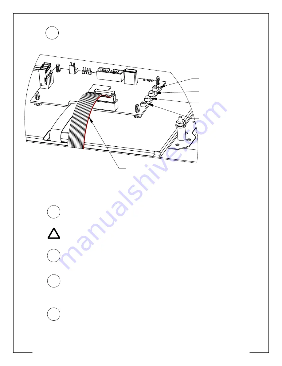
background image

Enter ColorDMD Menu

 /

Advance to Next Menu Item
Toggle Selection Up /

Confirm Menu Exit

Toggle Selection Down

Return to Previous Menu Item /

Initiate USB Download

(Press for 5 Seconds)

Red Stripe on the

14-Pin Ribbon Cable

Plug the 14-Pin ribbon cable into DMD_IN on the ColorDMD with the 

red stripe nearest the push-buttons

 (see Fig. F).  The other end 

of this cable should still be plugged into J-603 on the DMD 

Controller Board with red stripe on the left-hand side (see Fig. E).

12

Figure F

STEP

If pinball machine had a lamp board mounted to the speaker 

panel, the lamp board PCB must not make contact with the 

ColorDMD metal mounting bracket.

STEP

13

Locate and press the right-most 

ColorDMD Menu

 button (See Fig. F) 

to customize the display settings.  Continue pressing the button to 

advance to the "MOUNTING" menu.  Next use the 

Toggle Selection Up


button to change the setting to "WPC".

15

STEP

Double check for proper alignment of 

all

 cable connections.

For additional information regarding display settings please visit 

our website at 

www.colordmd.com

.

STEP

STEP

Press the right-most button to advance to the "EXIT AND SAVE" 

menu.  Press the 

Confirm Menu Exit

 button to save settings and 

return to game mode.  Video should appear on the new ColorDMD 

Display.  Visit ColorDMD website to download game specific color 

ROM file and install using USB thumb drive.  Have fun!

16

14

While ensuring no wires get pinched, raise the speaker panel 

and turn on the pinball machine.

ALL RIGHTS RESERVED - US PATENT 8,773,452 B2 - COPYRIGHT 2016 - COLORDMD DISPLAYS LLC

!

Summary of Contents for CHROMA eDP WPC

Page 1: ...D from the game and store it in a safe place 1 2 3 STEP STEP STEP Disconnect the DMD power and ribbon cables from the DMD Unplug the DMD power cable from the high voltage A V board J 604 see Fig E and remove this cable from the backbox Congratulations on the purchase of a new ColorDMD display The ColorDMD will enhance your pinball machine by introducing color to the dot matrix display graphics pro...

Page 2: ...protective film from the front side of the new ColorDMD display Use the original DMD mounting hardware from Step 3 to fasten the ColorDMD display to the speaker panel See Fig B for correct stacking order of the hardware Ensure the ground cable lug from Step 7 is sandwiched between metal bracket and one of the 5 8 black spacers 5 6 7 STEP STEP STEP WARNING Electric Shock Hazard To protect against a...

Page 3: ...e connector see Fig D Plug this connector into the PWR header see Fig C on the ColorDMD Plug the other end of the new ColorDMD Power Cable see Fig D into J 116 on the WPC Power Driver Board see Fig E If an existing cable is currently plugged into J 116 disconnect it before connecting the ColorDMD power cable If you disconnected a cable from J 116 in the previous step use the included male to male ...

Page 4: ...he right most ColorDMD Menu button See Fig F to customize the display settings Continue pressing the button to advance to the MOUNTING menu Next use the Toggle Selection Up button to change the setting to WPC 15 STEP Double check for proper alignment of all cable connections For additional information regarding display settings please visit our website at www colordmd com STEP STEP Press the right...

Reviews: