COHU 3230 series Installation Manual Download Page 3

3

6X-1086

3230 CAMERA

INSTALLATION MANUAL

1.0  GENERAL DESCRIPTION

This introduction briefly describes overall 

characteristics  of  the  Model 3230 Camera (figure 

1) related to its installation. Specifications can be 

found on the CD supplied with this camera.

1.1  Electrical Characteristics

The 3230 provides a highly sensitive CCD 

camera in an environmental housing.

This camera is available with either NTSC or 

PAL video output, depending on the model. Operat

-

ing power is either 12 V dc, 24 V dc/ac, or 115 V ac 

— again depending on the model.

An integrated camera module provides a 3.3 to 

99 mm zoom lens.

Data communications with the camera can be 

either RS-232 or RS-422 for control of DSP func

-

tions.

It has a day/night feature that increases sensi

-

tivity by reverting from color to monochrome output 

in low light conditions. This feature can be made to 

operate automatically or by manual control when 

desired.

A model number interpretation diagram ap

-

pears in figure 2. That diagram shows the various 

basic configurations of the 3230.

1.1.1  Initial Setup Software

Graphical User Interface (GUI) software is 

available for setting the address and performing 

field tests and setups for each camera. This is in

-

cluded on a CD provided with the camera. 

Technical manual 6X-1084, also included on 

the CD, is the reference manual for this GUI.

1.1.2 Camera Firmware Protocol  

Technical manual 6X-1085 provides the pro

-

tocol details for develop software for controlling 

the camera. This document is available on the CD 

provided with the camera. 

1.2  Mechanical Characteristics

Dimensions are shown in figure 5. The 3230 

consists of an IP67 environmentally sealed and 

pressurized camera module. Dry nitrogen is used 

for the presssurization. Dry desiccant packs are 

placed inside the camera during during the sealing 

process.

An integral sun shield over the camera housing 

minimizes heat build up from sun light.

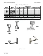
The mounting base (figure 5) for the 3230 has 

a five-hole in-line 1/4/20 pattern for attachment to a 

suitable base. 

A 3230 can be mounted on any one of five me

-

chanical configurations. The model number defines 

any mounting equipment that was supplied with the 

camera. Table 1 lists the mounting items supplied 

for each of the mounting configurations available 

with a 3230.

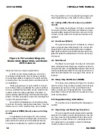
A Schrader valve (figure 7 — the car tire type 

air valve on the left) on the rear panel provides for 

pressurizing the housing with the dry nitrogen. 

The pressure relief valve, on the right, should 

be lifted off its seat during purging of the camera. 

This aids in the flow of gas through the housing 

while purging moisture laden air from inside.
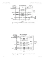
2.0  INSTALLATION

This section covers the general requirements 

of installing the 3230 including cabling and power 

requirements.  Section 5, toward the rear of this 

manual, covers several other items including static 

discharge protection and proper shipping and han

-

dling of the 3230. Figure 4 shows a typical intercon

-

nection diagram using RS-422 connections on the 

camera.

2.3  Equipment Supplied

The most basic configuration of the camera 

consists of only the camera, its sunshield, and a 

mating connector kit. This connector kit builds the 

system cable plug which connects to the camera 18 

pin MS type connector.

  Figure 3 shows the five optional mounts that 

can be ordered with the camera. The mount sup

-

plide with the camera will be reflected in the camera 

model number. 

2.4  Equipment Required but Not Supplied

As a minimum the 3230 requires a source of 

operating power, a monitor on which to view the 

Summary of Contents for 3230 series

Page 1: ...3230 SERIES ANALOG ENVIRONMENTAL CAMERA INSTALLATION MANUAL Technical Manual 6X 1086 March 21 2008 Figure 1 Model 3230 NTSC or PAL Camera RS 232 RS 422...

Page 2: ...able 1 Manual 6X 1084 The setup GUI for configuring camera characteristics 2 Manual 6X 1085 The protocol for use by programmers to write software for controlling camera functions CAUTION Do not power...

Page 3: ...ressurized camera module Dry nitrogen is used for the presssurization Dry desiccant packs are placed inside the camera during during the sealing process An integral sun shield over the camera housing...

Page 4: ...tly but these are not common devices 2 5 RS 422 and RS 232 Wiring Cable diagrams in this manual show pin func tions for both RS 232 and RS 422 connections Only one of these communications methods can...

Page 5: ...OUNT HEAVY DUTY WALL MOUNT NONE None Supplied PEDD Pedestal Mount CEIL Ceiling Mount POLE Pole Mount MAST Mast Mount HDWM Heavy Duty Wall Mount Note Read the table horizontally A dot designates an ite...

Page 6: ...ductor shielded cable must be used with this camera both to minimize EMI radiation and to reduce susceptibility to interference The cable must have an overall shield with at least 95 percent coverage...

Page 7: ...6X 1086 3230 CAMERA INSTALLATION MANUAL Figure 5 Dimensions Model 3230 Camera Camera Sunshield Dimensions...

Page 8: ...lation to power input requirements 1 The model 3232 operates from 12 V dc 10 percent 2 The model 3234 operates from either 24 V ac or 24 V dc 10 3 The model 3235 operates from 115 V ac 10 Power consum...

Page 9: ...el provides for all interconnections with the camera A mating plug kit is supplied for the system cable con necting to this rear panel connector 2 9 1 2 Schrader Valve A Schrader valve figure 7 the ca...

Page 10: ...d through any conduit or other re stricted passage on its way to the mounting location of the 3230 Or the cable could be pulled through conduit in the opposite direction if the other end has stripped...

Page 11: ...connec tors The web site for Coax Seal has complete infor mation about this product 3 0 CAMERA SETUP A GUI specific to the model 3230 provides all setup communications A separate manual describes fea...

Page 12: ...eners and a repositionable head at the bottom end to which the camera can be bolted for movement up down and right left 4 3 Pole Mount POLE The pole mount figure 11 attaches to vertical poles using st...

Page 13: ...AL Figure 9 Type 1310230 011 System Cable 18 pin MS Type Connector Kit Kit as Typically Packaged Connector Kit Contents Wiring Side Solder Cups Front Side Mating Sockets Connector Plug for the System...

Page 14: ...tock on the work bench surface 2 Connect the sheet stock to ground through a 1 megohm or greater value resistor 3 Use a wrist strap connected to ground through a 1 megohm or greater value resistor whe...

Page 15: ...15 6X 1086 3230 CAMERA INSTALLATION MANUAL Figure 10 Dimensions PEDD and CEIL Mounts Figure 11 Dimensions POLE Mount...

Page 16: ...16 6X 1086 3230 CAMERA INSTALLATION MANUAL Figure 12 Dimensions MAST Mount Figure 13 Dimensions HDWM Mount...

Page 17: ...BNC stripped leads RJ 45 24 V AC dc 19 CA 292A RS 232 stripped leads stripped leads stripped leads 20 CA 292B BNC stripped leads D9S 21 CA 293A RS 422 stripped leads stripped leads stripped leads 22 C...

Page 18: ...18 6X 1086 3230 CAMERA INSTALLATION MANUAL Figure 16 Type CA 254A System Interconnection Cable Figure 15 Type CA 253B System Interconnection Cable...

Page 19: ...19 6X 1086 3230 CAMERA INSTALLATION MANUAL Figure 18 Type CA 254M System Interconnection Cable Figure 17 Type CA 254B System Interconnection Cable...

Page 20: ...20 6X 1086 3230 CAMERA INSTALLATION MANUAL Figure 20 Type CA 292B System Interconnection Cable Figure 19 Type CA 292A System Interconnection Cable...

Page 21: ...21 6X 1086 3230 CAMERA INSTALLATION MANUAL Figure 22 Type CA 293B System Interconnection Cable Figure 21 Type CA 293A System Interconnection Cable...

Page 22: ...22 6X 1086 3230 CAMERA INSTALLATION MANUAL Figure 24 Type CA 295E System Interconnection Cable Figure 23 Type CA 293M System Interconnection Cable...

Page 23: ...23 6X 1086 3230 CAMERA INSTALLATION MANUAL Figure 26 Type CA 295G System Interconnection Cable Figure 25 Type CA 295F System Interconnection Cable...

Page 24: ...24 6X 1086 3230 CAMERA INSTALLATION MANUAL Figure 28 Type CA 296A System Interconnection Cable Figure 27 Type CA 295M System Interconnection Cable...

Page 25: ...25 6X 1086 3230 CAMERA INSTALLATION MANUAL Figure 30 Type CA 296C System Interconnection Cable Figure 29 Type CA 296B System Interconnection Cable...

Page 26: ...45 Signal to Noise 48 dB Lens Zoom 30x optical zoom 3 3 mm to 99 mm f 1 6 to f 3 2 Lens Focus Auto manual selectable Digital Zoom Up to 10x with smooth transition produces effective digital focal len...

Page 27: ...RS 422 4 wire half duplex RS 232 half duplex Environmental Temperature Operating 50 to 60 C 58 to 140 F Protection Rating Storage 30 to 60 C 22 to 140 F Humidity Up to 100 percent relative Altitude S...

Page 28: ...shall be repaired or replaced without charge This Warranty does not extend to Cohu equipment subjected to misuse accident neglect improper applica tion or repaired or altered other than by Cohu or unl...

Reviews: