12
6X-1086
3230 CAMERA
INSTALLATION MANUAL
likely have its own unique requirements.
A 3230 can be ordered with any one of five
mounting arrangements. One of these is related
to direct base plate mounting for the 3230 and the
remaining four use mounting arms and brackets for
an installation.
Before preparing to mount a 3230 it is impor
-
tant to have either pre-installed the system cable or
to have verified that the cable can be routed to the
location of the mounting assembly. This often re
-
quires pulling cable through conduit and other tight
places. It is also necessary to plan for weatherproof
-
ing any through-wall holes.
Note that the Pedestal mount and the Ceiling
mount are the same mechanical assembly. The only
difference is in which direction they are mounted.
4.1 Pedestal (PEDD) Mount (same as Ceiling
mount)
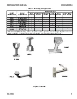
The pedestal mount (figure 10) has a round
bottom plate with four mounting holes and a move
-
able head at the other end of a pedestal column.
The head is adustable for up/down and right/left.
The hole pattern on the moveable head aligns with
the threaded holes on the bottom of the camera.
4.2 Ceiling (CEIL) Mount (same as pedestal
mount)
The ceiling mount (figure 10) has a round plate
for securing to the ceiling with four fasteners and a
repositionable head at the bottom end to which the
camera can be bolted for movement up/down and
right/left.
4.3 Pole Mount (POLE)
The pole mount (figure 11) attaches to vertical
poles using stainless steel straps. The curved arm
projecting from the mounting plate has an adjust
-
able head so that the mounted camera can be ad
-
justed in azimuth and elevation to cover the scene
of interest.
4.4 Mast Mount
The Mast mount (figure 12) straps to horizontal
arms. Stainless steel straps are used to secure the
mount to the arm. An adjustable head on the end of
a short pedestal provides for moving the camera in
azimuth and elevation for coverage of the scene of
interest.
4.5 Heavy Duty Wall Mount (HDWM)
This heavy duty wall mount (figure 13) secures
with two bolts. These holes are slotted so that final
alignment can be done in the event that the bolt
holes or studs are not perpendicular. A moveable
assembly on the end provides for movement in azi
-
muth and elevation.
5.0 Supplementary Information
This section covers handling the shipping the
camera.
5.1 Unpacking and Receiving Inspection
This item was thoroughly tested and carefully
packed in the factory. Upon acceptance by the car
-
rier, they assume responsibility for its safe arrival.
Should you receive this item in a damaged condi
-
tion, apparent or concealed, a claim for damage
must be made to the carrier.
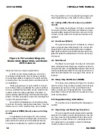
Figure 8. Pin Location Diagram,
Model 3232, Model 3234, and Model
3235 Cameras


