background image

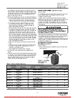
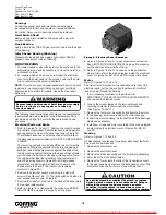
2. Run load hook down to its lowest position. Place the slack end

of chain in chain container. Do not remove the chain stop.

3. Place chain container flush against housing with chain

stripper between top lugs. Insert long attachment pin and
replace retaining clip.

4. Feed the remainder of chain into container by operating

hoist in the “UP” direction to the top limit. This will permit the
chain to pile freely and prevent the chain from kinking, which
may occur if the chain is placed in the container by hand.

OPERATION

This hoist is designed for safe operation within the limits of its
rated capacity. It is controlled by the “UP” and “DOWN” buttons
of the pushbutton station. Two-speed models utilize 2-step
buttons, the first step for operating the slow speed and the
second for the fast speed. Although the Coffing JLC is built with
many features to ensure safety, it is a requirement that a hoist
operator understands safe lifting practices. The following points
must be observed.

1. Do not overload the hoist.

2. Do not make extreme side pulls with the hoist.

3. Operate the hoist only in a hanging position with 

adequate support.

4. Do not “sling” the load hook and chain around the load.

Use an approved sling.

5. Be sure there are no twists in the load chain as it travels

into the hoist housing. This condition should be constantly
checked on double chain hoists because it is possible for the
load block to be “capsized” or turned over one or more times.

6. Before raising a load, always check to see that it is held

securely in the hook or sling chains, etc. Raise the load
only until the load chain is taut and then double check the
rigging before continuing to raise the load.

7. Do not stand beneath a load! Do not move a load in such a

manner as to endanger personnel.

8. Don’t lower into areas where visibility is obscured unless

someone else is guiding the operation.

9. Use common sense at all times when operating a hoist.

10. Do not operate if direction of hook travel is not the same as

indicated on button being pushed.

11. Do not operate unless hook travel limit devices function.

Test without load each shift.

12. Do not operate when hoist is not centered over load.

13. Do not operate if chain is not seated properly in sprockets

or sheave grooves.

14. Do not operate damaged or malfunctioning hoist.

OVERLOAD LIMITING PROTECTION

This hoist is equipped with a factory-calibrated overload
limiting clutch that will permit the lifting of loads within its rated
capacity, but will prevent the lifting of damaging overloads while
the hoist is being operated. If the load being lifted exceeds the
lifting capability of the overload clutch, the hoist motor will
continue to run, causing overheating of both the clutch and
hoist motor. This condition should be avoided by immediately
releasing the “UP” button and reducing the load to within the
rated capacity of the hoist. See GEARING, page 10, for
additional instructions on this device.

MAINTENANCE

INSPECTIONS

A planned inspection routine should be established for this
hoist based upon frequency of use, severity of use, and
environmental conditions (Reference ASME Standard B30.16).
Some inspections should be made frequently (daily to monthly)
and others periodically (monthly to yearly). It is strongly
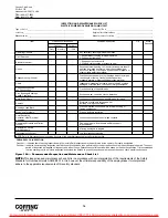
recommended that an Inspection and Maintenance Check List
and an Inspector’s Report, similar to those shown in Figures
10A and 10B, be used and filed for reference. All inspections
should be performed or overseen by a designated inspector.
Special inspections should be made following any significant
repairs or any operating occurrence leading one to suspect
that the hoist’s capability may have been impaired.

LOWERING WITHOUT POWER

If the power fails with a load suspended, the hoist will
automatically stop. In an emergency the load can be lowered
without power as follows:
1. DISCONNECT HOIST FROM POWER SUPPLY AND

REMOVE ELECTRICAL COVER.

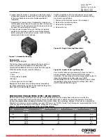
2. Refer to Figure 5. Open disc brake manually by using two

screwdriver blades, one on each side of the brake at a point
close to the brake spring posts. Apply pressure to the
underside of the armature plate (points “X”) to close the
solenoid and release the brake.

3. Use several quick releases instead of holding brake open

continuously. Do not exceed normal lowering speed.

6

Country Club Road
P.O. Box 779
Wadesboro, NC 28170 USA
TEL: (800) 477-5003
FAX: (800) 374-6853

Do not allow screwdriver blades to touch rotating
friction disc “C”.

Do not use hoist to lift, support or otherwise
transport people.

Do not allow the load to descend rapidly. This causes
the motor to race and serious damage may result.

The overload limiting clutch is an emergency
protective device and should not be used to measure
the maximum load to be lifted, or to sense the
overload imposed by a constrained load. While the
overload limiting clutch will protect the hoist from
damaging overloads, it will not ensure that a load is
within the rated capacity of the hoist.

Do not allow load to come in contact with the chain
container. If this situation exists reset the “UP” limit
switch so that the hook block stops below the chain
container (See LIMIT SWITCH ADJUSTMENT, page 8).

For more information contact: Sievert Crane and Hoist, (708) 771-1600, [email protected], www.sievertcrane.com

Summary of Contents for JLC Series

Page 1: ...to operate the equipment as directed in the manual may cause injury Should you have any questions regarding this product please call Coffing Hoists at 800 477 5003 Made in the U S A Before using the h...

Page 2: ...unless specific precautions have been taken 19 NOT allow the load chain or hook to be used as an electrical or welding ground 20 NOT allow the load chain or hook to be touched by a live welding elect...

Page 3: ...to ensure that the voltage at the reversing contactor does not drop below 10 of the nominal voltage while lifting a load Low voltage will result in higher amp draw damage to the hoist and potential fi...

Page 4: ...benches invite accidents 9 The operator should not engage in any practice which will divert his attention while operating the hoist 10 Before using the hoist the operator should be certain that all pe...

Page 5: ...according to LIMIT SWITCH ADJUSTMENT page 8 CHAIN CONTAINER Optional Accessary Refer to Table 4 For installations where the slack chain hanging from the hoist may be objectionable or hazardous the us...

Page 6: ...hile the hoist is being operated If the load being lifted exceeds the lifting capability of the overload clutch the hoist motor will continue to run causing overheating of both the clutch and hoist mo...

Page 7: ...UPPLY and remove the electrical cover 3 Using a screwdriver pry the spring guide plate out of the slots in the limit switch nuts See Figure 3 Turn the gold nut back to about the center of the threaded...

Page 8: ...nd silver respectively Each limit nut has 10 slots for fine adjustment and the increment of adjustment is such that one slot is equivalent to approximately one link of chain travel with the standard l...

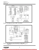
Page 9: ...ntacts If replacement is necessary see Figures 16 17 18 and 19 for replacement parts WIRING Refer to Figures 9A 9B 9C 9D Single phase units 115 230V are shipped wired for 115V and the 1 speed 230 460V...

Page 10: ...e as shown in Figure 6 3 Remove the transformer bolted to the back of the panel plate if it requires replacement 4 Refer to Figure 15 to disassemble the brake See BRAKE ADJUSTMENT on page 9 to properl...

Page 11: ...remove it to workbench 2 Remove the lug retaining screw 3 Remove the lug retainer 4 Remove the lug Care must be taken during reassembly to have the hook in proper orientation Refer to figures 8A 8B f...

Page 12: ...Check for burned contacts Replace as needed 4 Loose screw clamps 4 Ensure that screw clamps are tightened on the terminal blocks and reversing contactor Hook raises but will not lower 1 Hoist overload...

Page 13: ...hat the voltage at the reversing contactor is within 10 of the nominal voltage while lifting a load Motor brake noise or chatter while starting hoist 1 Hoist overloaded 1 Reduce load to within rated c...

Page 14: ...or 1 Speed 230 460V 3 Phase Models Figure 9C Wiring Diagram for 1 Speed 208V 380V 575V 3 Phase Models Factory supplied diagrams will be numbered beginning with 985 for 575V 987 for 208V and 988 for 38...

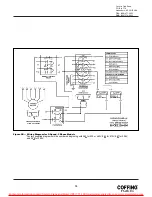
Page 15: ...3 Figure 9D Wiring Diagram for 2 Speed 3 Phase Models Factory supplied diagrams will be numbered beginning with 983 for 230 or 460V 985 for 575V 987 for 208V and 988 for 380V For more information cont...

Page 16: ...ssive wear Build up of foreign substances Housings Load Block Cracks distortion Excessive wear internal build up of foreign substances Wiring and Terminals Fraying defective insulation Hoist Reversing...

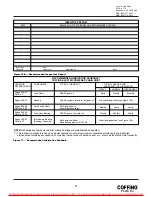
Page 17: ...dule RECOMMENDED LUBRICATION SCHEDULE COFFING ELECTRIC POWERED CHAIN HOIST PAGE AND COMPONENT TYPE OF LUBRICANT TYPE OF SERVICE AND REFERENCE NO FREQUENCY OF LUBRICATION HEAVY NORMAL INFREQUENT Pages...

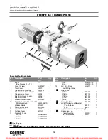
Page 18: ...JLC675K 20 1 15 JLC Strip Decal JLC677 1 Left Right Side Nylon Cover 1 8 ton 08770W 1 1 4 ton 08771W 1 1 2 ton 08772W 1 1 ton 08773W 1 2 ton 08774W 1 Chain Container 08348W 1 JLCET Trolley Lug Mounte...

Page 19: ...kwasher H4082P 4 Ref Description Part Qty Ref Description Part Qty No No No No Not available as an individual part Contact your nearest Coffing Service Center for parts and service For a complete list...

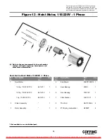
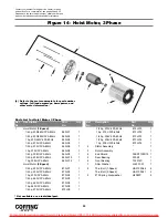
Page 20: ...60Hz 873JX12 1 1 4 hp 208V 3Ph 60Hz 873JX13 1 1 2 hp 208V 3Ph 60Hz 873JX14 1 1 hp 208V 3Ph 60Hz 873JX16 1 2 Stator Assembly 1 3 Rotor Assembly 1 4 End Shield 35EP3100D15 1 5 Rear Bearing 500K3 1 6 Fro...

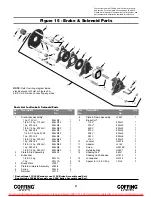
Page 21: ...JL6 1 415V 853JL7 1 10 Locknut H3978 3 11 Adapter JL142 1 12 Screw H2976P 3 13 Retaining Ring H5501 2 14 Shading Coil 860J1 2 Shading Coil Adhesive H7812 1 15 Lockwasher H4134 3 16 Spacer for 1 4 1 2...

Page 22: ...hase 4 cond 953JM1 1 11 PB Cable Assembly See Figures 18 19 1 12 Panel Standoff Spacer 200J4 3 13 1 4 Internal tooth Lockwasher H4134 3 14 1 4 20UNC X 4 Screw H1027P 3 15 8 32UNC X 5 16 Screw H2751 2...

Page 23: ...1 6 15 ft Power Cord Assembly 953JM1 1 7 PB Cable Assembly 1 See Figures 18 19 8 Panel Standoff 200J4 3 9 1 4 Internal tooth Lockwasher H4134 3 10 1 4 20UNC X 4 Screw H1027P 3 11 8 32UNC X 5 16 Screw...

Page 24: ...e For a complete list see pages 34 and 35 Please have the hoist model number serial number and part number with description available for reference 12 6 7 10 11 4 5 13 14 15 4 8 4 9 16 3 2 1 For more...

Page 25: ...t Assembly Includes items 6 7 36987 1 7 Button Assembly 36988 1 8 Grommet 36989 1 Hardware Kit 36939 1 Includes items 9 16 Warning Tag 687K3W 1 Parts List for 1 Speed Pushbutton Station Ref Descriptio...

Page 26: ...e For a complete list see pages 34 and 35 Please have the hoist model number serial number and part number with description available for reference 12 6 7 10 11 4 5 13 14 15 4 8 4 9 16 3 2 1 For more...

Page 27: ...t Assembly Includes items 6 7 36868 1 7 Button Assembly 36869 1 8 Grommet 36866 1 Hardware Kit 36939 1 Includes items 9 16 Warning Tag 687K3W 1 Parts List for 2 Speed Pushbutton Station Ref Descriptio...

Page 28: ...1 12 Retaining Ring H5520 1 13 Insulator JF754 1 14 Spring JF343 3 1 15 10 24UNC X 1 2 Screw H2970 2 Contact your nearest Coffing Service Center for parts and service For a complete list see pages 34...

Page 29: ...de Assembly 258JG7 1 18 End Plate 258J8 1 19 8 32UNC X 3 8 Screw H2741P 2 20 Drive Pinion 427J1 1 21 Retaining Ring H5520 1 22 10 24UNC X 3 8 Screw H2981P 2 Ref Description Part Qty Ref Description Pa...

Page 30: ...21 24 22 21 23 26 29 5 15 11 31 16 13 11 14 14 16 17 6 24 33 25 27 28 12 32 30 34 34 NOTE Orient output gear 32 with long boss towards gear housing 2 on 1 2 ton under models and towards transmission...

Page 31: ...Overload Clutch Assembly 1 8 ton 32 fpm 591JG22 1 1 4 ton 16 fpm 591JG25 1 1 4 ton 32 fpm 591JG22 1 1 2 ton 16 fpm 591JG16 1 1 2 ton 32 fpm 591JG21 1 1 2 ton 591JG17 1 24 Retaining Ring H5503 2 25 Be...

Page 32: ...have the hoist model number serial number and part number with description available for reference 2 Ton Models 1 Ton Under Models 1 4 5 3 2 6 9 18 8 19 15 14 26 24 15 28 32 12 29 7 25 31 16 14 30 23...

Page 33: ...22 3 8 24 Hex Locknut H3964P 2 23 Load Block Screw H2403P 2 24 Load Block Frame JF30 1 2 25 Sheave Shaft Assembly JF917 1 1 26 Sheave Shaft JF122 1 1 27 Sheave Bearing Assembly JF916 1 28 Roll Pin H5...

Page 34: ...st Otter Creek Rd Mabelville AR 72103 501 455 5898 Fax 501 455 6179 ARIZONA MECHANICS TOOL SERVICE 1301 E Apache Park Place Tuscon AZ 85714 520 889 8484 AZ only 800 372 6700 Fax 520 889 6668 CALIFORNI...

Page 35: ...5891 Fax 215 784 0343 RHODE ISLAND MOTORS HOIST CONTROLS INC 179 Railroad Street Woonsocket RI 02895 401 767 4568 Fax 401 767 4567 SOUTH CAROLINA ENGINEERED SYSTEMS INC 1121 Duncan Reidville Road Dun...

Page 36: ...ed by normal wear abuse improper or inadequate power supply improper or inadequate maintenance eccentric or side loading overloading chemical or abrasive actions excessive heat unauthorized modificati...

Reviews: