background image

Bearings

All bearings except hook and idler sheave bearings are
lubricated at the factory and should not require additional
lubrication. Noisy or worn bearings should be replaced.

Limit Switch Shaft

Remove any dirt accumulation and spray with a general
purpose lubricant.

Hook Bearing

Apply a few drops of SAE 30 gear or motor oil around the edge
of the bearing.

Idler Sheave Bearing (Bushing)

Disassemble load block and apply a light coat of NLGI #2
grease, or equivalent, inside of bearing.

HOIST REPAIRS

1. For major repairs or when the hoist is to be sectioned in the

suspension area, it will be necessary to move the hoist to a
workbench or table.

2. For repairs which can be done by removing the electrical

cover only, the hoist need not be moved. Lowering the hoist
to a convenient working level is desirable.

NOTE: If you do not have an experienced mechanic to do your
repair work, we recommend that you send your hoist to an
approved service station for repairs. Use authorized repair
parts only.

The following repair instructions will help you in understanding
repair procedures, when related to the Replacement Parts 
List starting on page 18. For clarity these are broken down 
into areas.

Electrical Parts and Brake

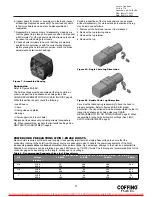
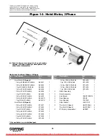
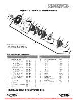
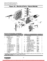
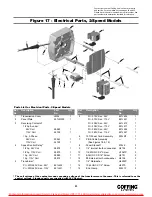
1. Refer to Figures 15, 16 and 17. Remove the cover to access

the controls. Single-phase models also have a starting switch
and capacitor mounted on the panel as shown in Figure 16.
The terminal blocks and end clamps snap off of the rails on
the plate using a small screwdriver. DO NOT SLIDE THE END
CLAMPS.

The reversing contactor can be slid off the rail, but it must be
snapped on. Where the contactor fits the rail, one side has
springs or pads that apply pressure against the edge of the
rail. By pressing against that side at the base of the contactor,
you can snap the part on or off using a rotating action. Note
the numbers that label the terminals on the contactor and
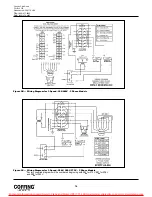
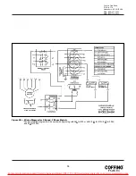
orient the part as shown in Figures 9A-9D. Single-phase
contactors have a small jumper that is not present on the 
3-phase (note the 3 and 5 terminals on the reversing
contactor in Figure 9A).

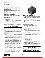
2. Remove the electrical panel by removing the stand-off

screws (See Figures 16 & 17). The limit switch and brake are
now accessible as shown in Figure 6.

3. Remove the transformer bolted to the back of the panel plate

if it requires replacement.

4. Refer to Figure 15 to disassemble the brake. See BRAKE

ADJUSTMENT on page 9 to properly set the brake.

5. Refer to Figures 20 and 21 to disassemble the limit switch.

See LIMIT SWITCH ADJUSTMENT on page 8 to properly
set the upper and lower limits of travel.

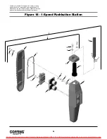
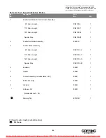
6. Refer to Figures 18 and 19 for repairs on the pushbutton

station. Also refer to the wiring diagram inside the electrical
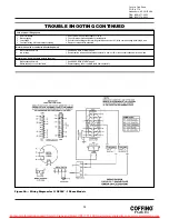
cover or Figures 9A, 9B, 9C and 9D for wiring instructions.

Motor

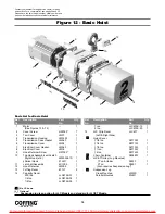
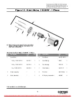
Refer to Figures 12, 13 and 14.

The hoist motor is located on the opposite end to that of the
electrical parts, but the two are tied together with electrical
leads running through the housing.
1. If it is necessary to replace or repair the motor,

DISCONNECT THE HOIST FROM THE POWER SUPPLY
and remove the electrical cover.

2. Loosen the screw clamps on the terminal blocks and

reversing contactor to disconnect the motor leads 
(See Figures 16 and 17).

3. Remove the four motor mounting bolts attaching the motor

to the housing. It will come loose at the motor coupling.

4. Inspect the motor coupling, motor shaft and all the bearings.

Replace as necessary.

5. Install new or repaired motor according to the wiring diagram

located inside the electrical cover or Figures 9A, 9B, 9C 
and 9D.

Gearing

Refer to Figures 7, 12 and 22.

As disassembly is extensive for gearing, disconnect the hoist
and move it to a workbench.
1. Remove the electrical cover.

2. Remove the electrical panel.

3. Remove the brake assembly and the limit switch assembly.

4. Drain the oil from the transmission.

5. Remove the four screws that attach the transmission cover

to the gear housing and remove the transmission cover. The
limit switch drive shaft will come along with the cover.

10

Country Club Road
P.O. Box 779
Wadesboro, NC 28170 USA
TEL: (800) 477-5003
FAX: (800) 374-6853

Remove load and disconnect hoist from power supply
before starting to do any repairs or to take any
sections apart.

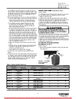
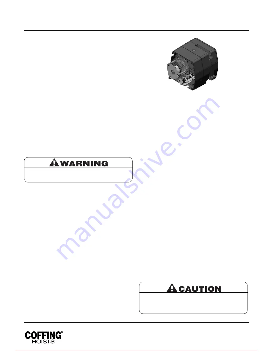
Figure 6 - Electrical Panel Removed

Do not disassemble or readjust the clutch, or replace
it with a clutch assembly from another hoist. Doing so
will void the warranty and may create an unsafe
condition. If replacement is needed due to wear or
loss of adjustment, always use a new clutch assembly.

For more information contact: Sievert Crane and Hoist, (708) 771-1600, [email protected], www.sievertcrane.com

Summary of Contents for JLC Series

Page 1: ...to operate the equipment as directed in the manual may cause injury Should you have any questions regarding this product please call Coffing Hoists at 800 477 5003 Made in the U S A Before using the h...

Page 2: ...unless specific precautions have been taken 19 NOT allow the load chain or hook to be used as an electrical or welding ground 20 NOT allow the load chain or hook to be touched by a live welding elect...

Page 3: ...to ensure that the voltage at the reversing contactor does not drop below 10 of the nominal voltage while lifting a load Low voltage will result in higher amp draw damage to the hoist and potential fi...

Page 4: ...benches invite accidents 9 The operator should not engage in any practice which will divert his attention while operating the hoist 10 Before using the hoist the operator should be certain that all pe...

Page 5: ...according to LIMIT SWITCH ADJUSTMENT page 8 CHAIN CONTAINER Optional Accessary Refer to Table 4 For installations where the slack chain hanging from the hoist may be objectionable or hazardous the us...

Page 6: ...hile the hoist is being operated If the load being lifted exceeds the lifting capability of the overload clutch the hoist motor will continue to run causing overheating of both the clutch and hoist mo...

Page 7: ...UPPLY and remove the electrical cover 3 Using a screwdriver pry the spring guide plate out of the slots in the limit switch nuts See Figure 3 Turn the gold nut back to about the center of the threaded...

Page 8: ...nd silver respectively Each limit nut has 10 slots for fine adjustment and the increment of adjustment is such that one slot is equivalent to approximately one link of chain travel with the standard l...

Page 9: ...ntacts If replacement is necessary see Figures 16 17 18 and 19 for replacement parts WIRING Refer to Figures 9A 9B 9C 9D Single phase units 115 230V are shipped wired for 115V and the 1 speed 230 460V...

Page 10: ...e as shown in Figure 6 3 Remove the transformer bolted to the back of the panel plate if it requires replacement 4 Refer to Figure 15 to disassemble the brake See BRAKE ADJUSTMENT on page 9 to properl...

Page 11: ...remove it to workbench 2 Remove the lug retaining screw 3 Remove the lug retainer 4 Remove the lug Care must be taken during reassembly to have the hook in proper orientation Refer to figures 8A 8B f...

Page 12: ...Check for burned contacts Replace as needed 4 Loose screw clamps 4 Ensure that screw clamps are tightened on the terminal blocks and reversing contactor Hook raises but will not lower 1 Hoist overload...

Page 13: ...hat the voltage at the reversing contactor is within 10 of the nominal voltage while lifting a load Motor brake noise or chatter while starting hoist 1 Hoist overloaded 1 Reduce load to within rated c...

Page 14: ...or 1 Speed 230 460V 3 Phase Models Figure 9C Wiring Diagram for 1 Speed 208V 380V 575V 3 Phase Models Factory supplied diagrams will be numbered beginning with 985 for 575V 987 for 208V and 988 for 38...

Page 15: ...3 Figure 9D Wiring Diagram for 2 Speed 3 Phase Models Factory supplied diagrams will be numbered beginning with 983 for 230 or 460V 985 for 575V 987 for 208V and 988 for 380V For more information cont...

Page 16: ...ssive wear Build up of foreign substances Housings Load Block Cracks distortion Excessive wear internal build up of foreign substances Wiring and Terminals Fraying defective insulation Hoist Reversing...

Page 17: ...dule RECOMMENDED LUBRICATION SCHEDULE COFFING ELECTRIC POWERED CHAIN HOIST PAGE AND COMPONENT TYPE OF LUBRICANT TYPE OF SERVICE AND REFERENCE NO FREQUENCY OF LUBRICATION HEAVY NORMAL INFREQUENT Pages...

Page 18: ...JLC675K 20 1 15 JLC Strip Decal JLC677 1 Left Right Side Nylon Cover 1 8 ton 08770W 1 1 4 ton 08771W 1 1 2 ton 08772W 1 1 ton 08773W 1 2 ton 08774W 1 Chain Container 08348W 1 JLCET Trolley Lug Mounte...

Page 19: ...kwasher H4082P 4 Ref Description Part Qty Ref Description Part Qty No No No No Not available as an individual part Contact your nearest Coffing Service Center for parts and service For a complete list...

Page 20: ...60Hz 873JX12 1 1 4 hp 208V 3Ph 60Hz 873JX13 1 1 2 hp 208V 3Ph 60Hz 873JX14 1 1 hp 208V 3Ph 60Hz 873JX16 1 2 Stator Assembly 1 3 Rotor Assembly 1 4 End Shield 35EP3100D15 1 5 Rear Bearing 500K3 1 6 Fro...

Page 21: ...JL6 1 415V 853JL7 1 10 Locknut H3978 3 11 Adapter JL142 1 12 Screw H2976P 3 13 Retaining Ring H5501 2 14 Shading Coil 860J1 2 Shading Coil Adhesive H7812 1 15 Lockwasher H4134 3 16 Spacer for 1 4 1 2...

Page 22: ...hase 4 cond 953JM1 1 11 PB Cable Assembly See Figures 18 19 1 12 Panel Standoff Spacer 200J4 3 13 1 4 Internal tooth Lockwasher H4134 3 14 1 4 20UNC X 4 Screw H1027P 3 15 8 32UNC X 5 16 Screw H2751 2...

Page 23: ...1 6 15 ft Power Cord Assembly 953JM1 1 7 PB Cable Assembly 1 See Figures 18 19 8 Panel Standoff 200J4 3 9 1 4 Internal tooth Lockwasher H4134 3 10 1 4 20UNC X 4 Screw H1027P 3 11 8 32UNC X 5 16 Screw...

Page 24: ...e For a complete list see pages 34 and 35 Please have the hoist model number serial number and part number with description available for reference 12 6 7 10 11 4 5 13 14 15 4 8 4 9 16 3 2 1 For more...

Page 25: ...t Assembly Includes items 6 7 36987 1 7 Button Assembly 36988 1 8 Grommet 36989 1 Hardware Kit 36939 1 Includes items 9 16 Warning Tag 687K3W 1 Parts List for 1 Speed Pushbutton Station Ref Descriptio...

Page 26: ...e For a complete list see pages 34 and 35 Please have the hoist model number serial number and part number with description available for reference 12 6 7 10 11 4 5 13 14 15 4 8 4 9 16 3 2 1 For more...

Page 27: ...t Assembly Includes items 6 7 36868 1 7 Button Assembly 36869 1 8 Grommet 36866 1 Hardware Kit 36939 1 Includes items 9 16 Warning Tag 687K3W 1 Parts List for 2 Speed Pushbutton Station Ref Descriptio...

Page 28: ...1 12 Retaining Ring H5520 1 13 Insulator JF754 1 14 Spring JF343 3 1 15 10 24UNC X 1 2 Screw H2970 2 Contact your nearest Coffing Service Center for parts and service For a complete list see pages 34...

Page 29: ...de Assembly 258JG7 1 18 End Plate 258J8 1 19 8 32UNC X 3 8 Screw H2741P 2 20 Drive Pinion 427J1 1 21 Retaining Ring H5520 1 22 10 24UNC X 3 8 Screw H2981P 2 Ref Description Part Qty Ref Description Pa...

Page 30: ...21 24 22 21 23 26 29 5 15 11 31 16 13 11 14 14 16 17 6 24 33 25 27 28 12 32 30 34 34 NOTE Orient output gear 32 with long boss towards gear housing 2 on 1 2 ton under models and towards transmission...

Page 31: ...Overload Clutch Assembly 1 8 ton 32 fpm 591JG22 1 1 4 ton 16 fpm 591JG25 1 1 4 ton 32 fpm 591JG22 1 1 2 ton 16 fpm 591JG16 1 1 2 ton 32 fpm 591JG21 1 1 2 ton 591JG17 1 24 Retaining Ring H5503 2 25 Be...

Page 32: ...have the hoist model number serial number and part number with description available for reference 2 Ton Models 1 Ton Under Models 1 4 5 3 2 6 9 18 8 19 15 14 26 24 15 28 32 12 29 7 25 31 16 14 30 23...

Page 33: ...22 3 8 24 Hex Locknut H3964P 2 23 Load Block Screw H2403P 2 24 Load Block Frame JF30 1 2 25 Sheave Shaft Assembly JF917 1 1 26 Sheave Shaft JF122 1 1 27 Sheave Bearing Assembly JF916 1 28 Roll Pin H5...

Page 34: ...st Otter Creek Rd Mabelville AR 72103 501 455 5898 Fax 501 455 6179 ARIZONA MECHANICS TOOL SERVICE 1301 E Apache Park Place Tuscon AZ 85714 520 889 8484 AZ only 800 372 6700 Fax 520 889 6668 CALIFORNI...

Page 35: ...5891 Fax 215 784 0343 RHODE ISLAND MOTORS HOIST CONTROLS INC 179 Railroad Street Woonsocket RI 02895 401 767 4568 Fax 401 767 4567 SOUTH CAROLINA ENGINEERED SYSTEMS INC 1121 Duncan Reidville Road Dun...

Page 36: ...ed by normal wear abuse improper or inadequate power supply improper or inadequate maintenance eccentric or side loading overloading chemical or abrasive actions excessive heat unauthorized modificati...

Reviews: