background image

5

Description;

Detail no;

Pos. no;

Amount/ detail;

Heating element 2200W

160107

1

1

Solenoid valve

160230-05

2

1

Silicone grommet

160537-03

3

1

Plug solenoid valve

160538-03

3

2

Nipple ¼” x 8 mm

180158

4

1

Silicon hose non return valve L=37 cm 150501

5

1

Silicon hose mixing bowl

    L=32 cm 150501

6

1

Silicon hose drainage

    L=42 cm 150501

7

1

Silicon hose spillway overfl    L=35 cm

150501

8

1

Canister

1205621

9

1

Plastic finger guard

160418

10

1

Fan

160415

11

1

Cold water hose

1505032

12

1

Power cable cord with plug

160522

13

1

Motor gear

160465

14

1

Inlet valve

120624-01

15

1

Foot support

1203202

16

4

Relay

160245

17

2

Whipper motor

160460-02

18

1

Switch 2pol

160801-04

19

1

Slinger disc

120480

20

1

Clip on base

120478

21

1

Impellor

120484

22

1

Whipper chamber

120486

23

1

Mixing bowl

1204851

24

1

Steam trap

120487

25

1

Location pillar

120482

26

2

Micro switch

160840-01

27

1

Push-button switch

160817

28

1

Push-button switch

160817

29

1

Time relay

160228-01

31

1

Dust filter

120134

32

1

Chute left

120489

33

1

Knob for thermostat

160812

34

1

Rubber lead in

160542

35

1

Silicon gasket

150118-02

36

1

Level sensor

120613

37

1

High limit control

220220

38

1

Thermostat

160214

39

1

O-ring 2,8x33

120635

40

1

Whipper spindle seal

120655-02

41

1

Tidrelä tillslags fördröjt

160248

42

1

 Spare parts list

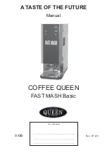
FAST MASH Basic

Summary of Contents for FAST MASH Basic

Page 1: ...Rev 071214 A TASTE OF THE FUTURE Manual Your retail dealer S GB FAST MASH Basic COFFEE QUEEN ...

Page 2: ... noise stops Pre set temp is 85 C 6 Add mash concentrate to the canister 7 The machine is ready to use after approx 15 minutes Do not serve mash before water have the right serving temperature 85 C NOTE Check that chute from the canister will be in close contact with steam trap Operation 1 Place the stainless bracket for mash trough on the two fixing screws at machines front 2 Put a mash trough in...

Page 3: ...e to fail The machine should stand on a flat surface so that it will function properly The machine should be placed on a waterproof surface so that any leakage is easily noticeable Make sure there is no bend on the connection tube when the machine is pushed into its place The tube connections should be regularly checked Make sure that no leakage has occurred in connection with installation Do not ...

Page 4: ...hese parts and assemble the machine Daily cleaning 1 Open door and loose A Steam trap B Mixer bowl C Whipper chamber D Whipper E Assembly plate Canister Chute F O ring assembly plate G Grommet whipper pin Drip tray 2 Dish all these parts Spray after that with a disinfectant Wait approximately 2 minutes After that flush all parts with water to make sure that rests of disinfectant disappears 3 Wash ...

Page 5: ...120624 01 15 1 Foot support 1203202 16 4 Relay 160245 17 2 Whipper motor 160460 02 18 1 Switch 2pol 160801 04 19 1 Slinger disc 120480 20 1 Clip on base 120478 21 1 Impellor 120484 22 1 Whipper chamber 120486 23 1 Mixing bowl 1204851 24 1 Steam trap 120487 25 1 Location pillar 120482 26 2 Micro switch 160840 01 27 1 Push button switch 160817 28 1 Push button switch 160817 29 1 Time relay 160228 01...

Page 6: ...Exploded view COFFEE QUEEN FAST MASH Basic 6 ...

Page 7: ...7 ELECTRICAL DIAGRAM FAST MASH Basic ...

Page 8: ...SERVICE Please contact your retail dealer Art no xxx xxxx Fast Mash Basic COFFEE QUEEN AB Box 960 671 29 ARVIKA besöksadress Korpralsv 1B Tel vxl 46 0 570 47700 Fax 46 0 570 47719 E mail info coffeequeen se www coffeequeen se ...

Reviews: