background image

Page 3 of  6

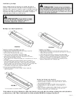
FIGURE 4

FIGURE 5

TOP VIEW

SIDE VIEW

Standard Mounting without Shroud:

MOUNTING WITH VHB TAPE:

1. Carefully remove the light head from the shroud.

    CAUTION: gently release the locking tabs to avoid breaking the tabs shown in

    Figure A .

2. Clean the light head brackets with supplied alcohol wipe.

    * for extra adhesion, see notes below.

3. Remove one side of the adhesive liner & apply to both brackets. Apply light pressure   

    for 20 seconds.

4. Insert bracket as shown on Figure B.

5. WITHOUT removing the second adhesive liner, hold the product to desired location.   

    Adjust the light head to its desired angle by adjusting the bracket.

6. Clean mounting surface with supplied alcohol wipe.

    *for extra adhesion, see notes below.

7. Remove the second adhesive liner.

8. Apply product on to the treated surface. Apply light pressure for 20 seconds.

9. Insert the provided screws in the light head locking mechanism as shown in Figure C.   

    This will hold the brackets in position & the light head in the desired angle.

MOUNTING WITH SUCTION CUP:

1. Carefully remove the light head from the shroud.

    CAUTION: gently release the locking tabs to avoid breaking the tabs shown on

    Figure A.

2. Remove the suction cups from the shroud mounting brackets. 

3. Install each suction cup to each bracket using the existing screws as shown on

    Figure D.

4. Insert bracket as shown on Figure B.

5. Clean mounting surface with supplied alcohol wipe.

6. Apply the product on to the treated surface gently pressing the suction cups on to the

    glass. Apply light pressure for 20 seconds. Gently adjust the light head to its desired  

    angle if needed.   

7. Insert the provided screws in the light head locking mechanism as shown in Figure C. 

    This will hold the brackets in position & the light head in the desired angle.

MOUNTING WITH HARDWARE (HARDWARE NOT PROVIDED):

1. Carefully remove the light head from the shroud.

    CAUTION: gently release the locking tabs to avoid breaking the tabs shown on   

    Figure A.

2. Insert the light head bracket as shown on Figure B.

3. Hold the product to desired location. Adjust the light head to its desired angle

    by adjusting the bracket.

4. Clean mounting surface with supplied alcohol wipe.

5. Install product on to the treated surface by using #8 hardware screw (not

    included) as shown on Figure E.

6. Insert the provided screws in the light head locking mechanism as shown in Figure C.

    This will hold the brackets in position & the light head in the desired angle.

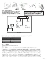
FIGURE 6

FIGURE 7

FIGURE 8

** MOUNTING HARDWARE NOT PROVIDED

*For extra adhesion, use 3M Tape Primer. For product & application information, go to: https://multimedia.3m.com/

mws/media/65952O/3mtm-tape-primer-94.pdf

Summary of Contents for CD5051VDL Series

Page 1: ...artment doors people vehicles or other obstructions 6 The use of this or any other warning device does not ensure all drivers can or will observe or react to a warning signal Never take the right of w...

Page 2: ...Once desired angle is achieved gently tighten the fastener using a 10mm wrench or socket 8 Clean mounting surface with supplied alcohol wipe for extra adhesion see notes below 9 Remove the second adhe...

Page 3: ...kets 3 Install each suction cup to each bracket using the existing screws as shown on Figure D 4 Insert bracket as shown on Figure B 5 Clean mounting surface with supplied alcohol wipe 6 Apply the pro...

Page 4: ...le of syncing with other compatible CODE 3 products by following these steps 1 Set the desired flash pattern on each unit individually It is also strongly recommended that the same style of flash patt...

Page 5: ...C N C N C N C N C N C N C N C N C 33 Double Flash Simultaneous Color 2 A 120 Class 1 Class 1 Class 1 Class 1 N C N C N C N C N C N C N C N C 34 Double Flash Simultaneous Color 2 B 120 Class 1 Class 1...

Page 6: ...PPLY TO THE PRODUCT BUYER S SOLE AND EXCLUSIVE REMEDY IN CONTRACT TORT OR UNDER ANY OTHER THEORY AGAINST MANUFACTURER REGARDING THE PRODUCT AND ITS USE SHALL BE THE REPLACEMENT OR REPAIR OF THE PRODUC...

Page 7: ...tivo de advertencia no garantiza que los conductores puedan respetar la se al de alarma o reaccionar ante ella o vayan a hacerlo Nunca d por hecho que tiene prioridad de paso Es responsabilidad del op...

Page 8: ...miento del adhesivo sujete el producto en la ubicaci n deseada Afloje y apriete con la mano la tuerca seg n sea necesario para ajustar el ngulo del cabezal de luz Una vez que logre el ngulo deseado ap...

Page 9: ...que se muestran en la Figure A 2 Retire las ventosas de los soportes de montaje de la cubierta 3 Instale cada ventosa en cada soporte con los tornillos existentes como se muestra en la Figure D 4 Inse...

Page 10: ...s cables azul y negro para cambiar el patr n de destello Funci n de atenuaci n Conecte el cable azul al cable de alimentaci n rojo Sincronizaci n La serie CD5051VDL es capaz de sincronizarse con otros...

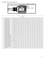
Page 11: ...P gina 5 de 6 SELECCIONAR PATR N ENCENDIDO COLOR 2 APAGADO ENCENDIDO COLOR 1 Selecci n de patr n de parpadeo Adaptador de cigarrillos...

Page 12: ...N CUALQUIER SUPUESTO EN CONTRA DEL FABRICANTE RESPECTO AL PRODUCTO Y SU USO SER EL REEMPLAZO O LA REPARACI N DEL PRODUCTO O EL REEMBOLSO DEL PRECIO DE COMPRA PAGADO QUE HAYA PAGADO EL COMPRADOR POR E...

Page 13: ...utilisation de ce dispositif ou de tout autre dispositif d avertissement ne garantit pas que tous les conducteurs seront attentifs aux signaux ou qu ils r agiront cons quemment un signal d urgence Ne...

Page 14: ...SANS retirer le deuxi me film adh sif maintenir le produit l emplacement souhait Desserrer et serrer la main l crou selon les besoins pour r gler l angle de la t te d clairage Une fois l angle souhait...

Page 15: ...ue ventouse sur chaque support l aide des vis existantes comme indiqu la Figure D 4 Ins rer le support comme indiqu la Figure B 5 Nettoyez la surface de montage avec la lingette base d alcool fournie...

Page 16: ...fil d alimentation rouge Synchronisation La s rie CD5051VDL est capable de se synchroniser avec d autres produits CODE 3 compatibles en suivant ces tapes 1 R gler le sch ma de clignotement souhait sur...

Page 17: ...Page 5 sur 6 S LECTION DE MOD LE ON COULEUR 2 DE ON COULEUR 1 S lection du mod le de clignotement ADAPTATEUR CIGARETTE...

Page 18: ...SELON TOUTE AUTRE TH ORIE EN CE QUI CONCERNE LE PRODUIT ET SON UTILISATION SE LIMITERONT LA DISCR TION DU FABRICANT AU REMPLACEMENT OU LA R PARATION DU PRODUIT OU AU REMBOURSEMENT DU PRIX D ACHAT PAY...

Page 19: ...n Personen Fahrzeuge oder andere Hindernisse blockiert wird 6 Durch die Verwendung dieser oder anderer Warnvorrichtungen kann nicht gew hrleistet werden dass alle Verkehrsteilnehmer das Notfallwarnsig...

Page 20: ...tter vorsichtig mit einem 10 mm Schrauben oder Sechskantschl ssel an 8 Reinigen Sie die Montagefl che mit dem mitgelieferten alkoholgetr nkten Tuch F r zus tzliche Haftung siehe Hinweise unten 9 Entfe...

Page 21: ...gn pfe wie in Abb D dargestellt an den Halterungen mit den vorhandenen Schrauben 4 Bringen Sie die Halterung wie in Abb B dargestellt an 5 Reinigen Sie die Montagefl che mit dem mitgelieferten alkohol...

Page 22: ...g Die CD5051VDL Serie kann mithilfe der folgenden Schritte mit anderen kompatiblen CODE 3 Produkten synchronisiert werden 1 Stellen Sie das gew nschte Leuchtmuster f r jedes Ger t einzeln ein Es wird...

Page 23: ...Seite 5 von 6 MUSTER AUSW HLEN EIN FARBE 2 AUS EIN FARBE 1 Auswahl des Leuchtmusters ZIGARETTENADAPTER...

Page 24: ...WENDUNG BESTEHEN NACH ERMESSEN VON DER HERSTELLER IM ERSATZ ODER IN DER REPARATUR DES PRODUKTES ODER IN DER R CKERSTATTUNG DES KAUFPREISES DEN DER K UFER F R DAS NICHT KONFORME PRODUKT BEZAHLT HAT UNT...

Reviews: