Cobra CB6 Service Manual Download Page 24

20 

Exploded Parts Diagrams 

Revision 2 

© 

Moffat Ltd, August 2012 

Cobra Series Gas Barbeque 

8.1 CB6 

Gas 

Barbeque 

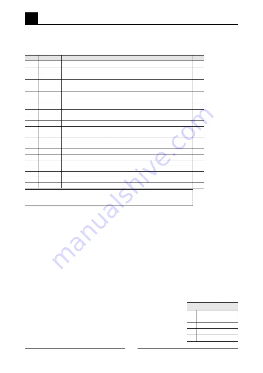
8.1.1  CB6 - Main Assembly 

* Recommended  Parts  Level  

RPL 

Number of units in service  

B 5-10 

C 10-50 

A 1-5 

D 50+ 

Item  Part No. 

Description 

*RPL 

229883 

SIDE PANEL LH 

229882 

SIDE PANEL RH 

229879 

FRAME WA 

230585 

SPLASHBACK 

5  

227445  

BURNER SUPPORT  

1)


5  

233729 

BURNER SUPPORT  

2)


231479 

BACK PANEL 

229870 

RADIENT CASTING COBRA 

230587 

COBRA BADGE 

229869 

GRATE COBRA 

10 

229860 

INNER RADIATION PANEL 

11 

230584 

HOB FRONT WA 

12 

230513 

CONTROL PANEL 

13 

230586 

PIZEO IGNITOR 

14 

228047 

HT LEAD 


229731     HT LEAD 250mm RING TERMINAL 

(from serial# 472383)


15 

229951 

DRIP TRAY 

16 

230579 

BASE PANEL 

17 

230577 

LEG MTG PLATE COBRA 

18 

234059 

LEG 2INCH ASSEMBLY COBRA 

19 

229674 

REAR ROLLER ASSEMBLY 

20 

229671 

LEG RING PLATE THREADED 

  1) 

Up to Lot.No 0924xxx  (Not interchangeable)  


2) 

From Lot.No 0925xxx  (Not interchangeable)  

Summary of Contents for CB6

Page 1: ...Revision 2 Moffat Ltd August 2012 Cobra Series Gas Barbeque Service Manual Gas Barbeque Model CB6 ...

Page 2: ...s and those special cases where these settings are required to change this manual gives a full explanation as to how and what effects will result MAKING ALTERATIONS MAY VOID WARRANTIES AND APPROVALS IMPORTANT WARNING ALL INSTALLATION AND SERVICE REPAIR WORK MUST BE CARRIED OUT BY QUALIFIED PERSONS ONLY IMPROPER INSTALLATION ADJUSTMENT ALTERATION SERVICE OR MAINTENANCE CAN CAUSE PROPERTY DAMAGE INJ...

Page 3: ...Revision 2 Moffat Ltd August 2012 Cobra Series Gas Barbeque ...

Page 4: ...ol System 4 Maintenance 9 Cobra Gas Barbeque Maintenance Schedule 5 Fault Finding 10 5 1 Fault Finding Table 5 2 Fault Diagnosis 6 Service Procedures 12 6 1 Access 6 2 Replacement 6 3 Adjustment Calibration 7 Accessories 18 Gas Conversion Kits 8 Exploded Parts Diagrams 19 8 1 CB6 Gas Barbeque 9 Service Contacts 21 Appendix A Gas Type Conversion 23 Appendix B Equipment Design Changes 28 Contents ...

Page 5: ...75 4 50 kPa 4 5 13 5 w c 11 18 w c 0 95 kPa 2 60 kPa 3 8 w c 10 0 w c Gas Connection BSP Male Burner Operating Pressure Town Gas 66 0 MJ hr 62 500 Btu hr 0 75 1 50 kPa 3 6 w c 0 63 kPa 2 5 w c Nat Gas G20 Propane G31 Heat Input nett Nominal 18 0 kW 18 0 kW Reduced 6 0 kW 6 4 kW Gas Rate nett Nominal 1 90 m3 hr 1 40 kg hr Reduced 0 63 m3 hr 0 50 kg hr Supply Pressure 20 mbar 37 mbar Burner Operatin...

Page 6: ...2 1 Specifications Revision 2 Moffat Ltd August 2012 Cobra Series Gas Barbeque External Dimensions CB6 Barbeque 600mm ...

Page 7: ... warranty Components having adjustments protected e g paint sealed by manufacturer are only allowed to be adjusted by an authorised service agent They are not to be adjusted by the installation person Unpacking Remove all packaging and transit protection from the appliance including all protective plastic coating from the door outer panel and exterior stainless steel panels Check equipment and par...

Page 8: ...llation a The Gas Type the appliance has been supplied for is shown on coloured stickers located above the gas entry point and next to the rating plate Check that these are correct for the gas supply the appliance is being installed for The gas conversion procedure is detailed in the Gas Conversion and Specification section of this manual b The Supply Pressure required for this appliance is shown ...

Page 9: ...level and at the correct height 6 Connect the gas supply to the appliance 7 Check gas operating pressure is as shown in Specifications section 8 Check all gas connections for leakages using soapy water or other gas detecting equipment NOTE The operating pressure to be measured at the manifold test point and with two burners operating at the High Flame setting 9 Turn off the mains gas supply and bl...

Page 10: ...urner Operation b Ensure that the operator has been instructed in the areas of correct lighting operation and shutdown procedure for the appliance 2 The User Manual must be kept by the owner for future reference and a record of Date of Purchase Date of Installation and Serial Number of Unit recorded and kept with the manual These details can be found on the rating plate attached to the underside o...

Page 11: ...ng of Installation Operation and Servicing Gas Control Knobs OFF Position PILOT Burner HIGH Flame LOW Flame Piezo Igniter with burner flame viewing ports 3 1 Description of Controls Figure 3 1 3 2 Explanation of Control System thermocouple will cool after about 10 to 30 seconds and stop generating millivolts The electromagnet will then de energize and the plunger will snap shut cutting off the flo...

Page 12: ...nerates millivolts when heated The thermocouple screws into a fitting at the back of the gas valve to make an electric connection By pressing in the gas control knob the plunger can be temporarily held open while lighting There are two reasons for this firstly gas has to flow through the safety valve to make it possible to light the pilot burner and secondly the plunger has to be pushed all the wa...

Page 13: ...eck burner aeration shutters are adjusted to achieve correct flame 6a Inspect the thermocouples 6b Replace the thermocouples every 12 months 7 Check injectors are clean and free from blockages 8 Re grease gas cocks 9 Check for tightness of gas connections 10 Check for gas leaks 11 Check the piezo ignition of both pilots functions correctly Service Comments Additional work repairs required Customer...

Page 14: ... 5 2 2 Faulty gas control valve Check supply adjust pressure Replace the thermocouple Refer Section 6 2 1 Replace the gas control valve Refer Section 6 2 9 Main burners will not light Wrong size or blocked injectors Faulty gas control valve Incorrect supply pressure Replace clean injectors Refer Section 6 2 6 Replace the gas control valve Refer Section 6 2 9 Check supply correct pressure Burner go...

Page 15: ...racture and should be replaced Piezo Ignitor Faulty If no spark at all can be generated remove piezo ignitor and hold close to cabinet body depress piezo ignitor and if a spark cannot be generated to cabinet body the piezo ignitor is faulty and should be replaced NOTE If piezo ignition fails the pilots can be manually lit in the interim until the piezo circuit is repaired A standard taper torch or...

Page 16: ...Main Burner Injectors 15 6 2 7 Piezo Ignitor 15 6 2 8 H T Lead 15 6 2 9 Gas Control Valve 16 6 2 10 Gas Control Magnet 16 6 3 Adjustment Calibration 17 6 3 1 Gas Control Valve Re Greasing 17 6 3 2 Low Fire Rate Adjustment 17 WARNING ENSURE THAT THE GAS SUPPLY IS SWITCHED OFF BEFORE COMMENCING SERVICING ALWAYS CHECK TEST FOR GAS LEAKS ON COMPLETION OF SERVICING REPAIRS ON THE GAS SYSTEM CAUTION All...

Page 17: ...ap screws securing control panel to barbecue 3 Panel can now be removed from unit 4 H T leads may be required to be disconnected if control panel is to be removed away from the BBQ 1 Remove the control panel refer 6 1 1 2 Undo the thermocouple from the pilot assembly 3 Undo the thermocouple from the gas control valve The thermocouple can now be removed 4 Replace and re assemble in reverse order Fi...

Page 18: ...efer 6 1 1 2 Remove thermocouple piezo and pilot supply tube and injector from the pilot burner 3 Remove the two screws securing the pilot burner to the barbecue Figure 6 2 4b Thermocouple Gas Pilot Line H T Piezo Lead Two Screws Pilot Injector 6 2 3 Spark Electrode 1 Remove the control panel refer 6 1 1 2 Remove HT lead from spark electrode 3 Remove spark electrode from pilot burner 4 Replace and...

Page 19: ... 6 1 1 2 Remove the HT lead from the piezo ignitor by pulling firmly away 3 Unscrew the nut securing the piezo ignitor to the control panel Figure 6 2 7 4 Replace and re assemble in reverse order 1 Remove the top grate and radiant castings relevant to the burner to be removed 2 Slide the burner out from its supports 3 Replace and re assemble in reverse order Main Burner 6 2 8 H T Lead 1 Remove the...

Page 20: ...7 Replace and re assemble in reverse order Figure 6 2 9 Magnet Rear Nut 6 2 10 Gas Control Magnet 1 Remove the control panel refer 6 1 1 2 Undo the pilot supply main supply and disconnect the pilot thermocouple from the gas control valve 3 Undo the compression nut securing the gas control valve to the manifold assembly 4 Replace gas control and re assemble in reverse order NOTE Ensure that the cor...

Page 21: ...ose pliers or similar pull out gas control spindle again noting its orientation 4 Apply a suitable high temperature gas cock grease or lubricant such as ROCOL A S P Anti scuffing paste Dry Moly Paste to the outside of the spindle 5 Replace the spindle and re assemble gas control in reverse order 6 3 2 Low Fire Rate Adjustment 1 Remove the control panel refer 6 1 1 2 Light barbecue and set gas cont...

Page 22: ...obra Series Gas Barbeque GAS CONVERSION KITS INDEX AU NZ XP Models Only UK Models Only Model Gas Type to Convert to LP Gas Propane Nat Gas Butane Town Gas CB6 231562 231561 231563 231564 Model Gas Type to Convert to LPG Propane Nat Gas CB6 231562 231561 ...

Page 23: ...19 8 Exploded Parts Diagrams Revision 2 Moffat Ltd August 2012 Cobra Series Gas Barbeque 8 1 CB6 Gas Barbeque 8 1 1 CB6 Main Assembly ...

Page 24: ...BURNER SUPPORT 2 D 6 231479 BACK PANEL D 7 229870 RADIENT CASTING COBRA D 8 230587 COBRA BADGE D 9 229869 GRATE COBRA D 10 229860 INNER RADIATION PANEL D 11 230584 HOB FRONT WA D 12 230513 CONTROL PANEL D 13 230586 PIZEO IGNITOR A 14 228047 HT LEAD A 229731 HT LEAD 250mm RING TERMINAL from serial 472383 A 15 229951 DRIP TRAY C 16 230579 BASE PANEL D 17 230577 LEG MTG PLATE COBRA D 18 234059 LEG 2I...

Page 25: ...OR 0 75 TG A 27 019218 THERMOCOUPLE 450MM A 28 230319 FLEX TUBE 12 X1 4 OD S S D 29 026060 PRESSURE TEST SCREW PLUG B 30 230608 KNOB ASSY BBQ TOASTER B 31 022686 6 FLEXITUBE D 227559 OLIVE 3 8 227560 NUT 3 8 015152 OLIVE 3 8 015153 NUT 3 8 32 227375 INJECTOR MOUNTING BUSH D 33 025093 LOCK NUT M14x1 D 34 037270 INJECTOR 2 70mm NAT C 037165 INJECTOR 1 65mm LPG C 037155 INJECTOR 1 55mm BUTANE C 03445...

Page 26: ...pare Parts Free Call 1800 337 963 Fax 03 9518 3895 WESTERN AUSTRALIA MOFFAT PTY 67 Howe St Tel 08 9202 6820 Osbourne Park WA 6017 Fax 08 9202 6836 Spare Parts Free Call 1800 337 963 Fax 03 9518 3895 NATIONAL COVERAGE FOR 24 HOUR SERVICE OR MAINTENANCE DIAL FREE CALL 1800 622 216 AUSTRALIA ONLY Canada SERVE CANADA 22 Ashwarren Rd Tel 416 631 0601 Downview Fax 416 631 0315 Ontario M3J1Z5 New Zealand...

Page 27: ... LTD Unit 67 Gravelly Business Park Gravelly Park Birmingham B24 8TQ Tel 0121 327 5575 England Fax 0121 327 9711 United States of America MOFFAT INC 3765 Champion Blvd Winston Salem Tel 1800 551 8795 NC27115 Fax 336 661 9546 NATIONAL COVERAGE FOR SERVICE OR MAINTENANCE DIAL FREE CALL 1800 551 8795 USA ONLY ...

Page 28: ...crews on the front lower edges of the control panel and remove the panel from the front of the barbeque 3 Remove the barbeque grates and inner radiants to reveal the main burners 4 Carefully push the main burners forward and negotiate between the shield brackets fitted over the end of the burners and remove the burners from the barbeque to reveal the main burner injectors 5 Unscrew the main burner...

Page 29: ...nnect the gas supply tube to the base of the pilot burner and tighten Low Fire Adjustment 1 To set the burner low fire adjustment the low fire adjustment screw on the gas control valve should be screwed fully in then un screwed by the measurement shown in the Gas Specifications table at the end of this section NOTE The Low Fire Adjustment Screw should be sealed with coloured paint on completion of...

Page 30: ...other gas detecting equipment 2 Check the following functions in accordance with the operating instructions specified in the Operation section of this manual Light the Pilot Burners Light the Main Burners Check the Low Fire burner operation Check the High Fire burner operation Ensure that all the controls operate correctly Ensure that the operating pressure remains correct NOTE If for some reason ...

Page 31: ... fitted to the cap 4 Screw the cap back into the regulator Town Gas Only 1 Unscrew and remove the slotted cap from the regulator 2 Turn on the gas supply and the appliance 3 Adjust the pressure adjusting nut to achieve the correct burner operating pressure NOTE The operating pressure to be measured at the manifold test point and with both burners operating at the High Flame setting 4 Turn Off the ...

Page 32: ...cifications section of this manual for further details Natural Gas LP Gas Propane Butane Town Gas Main Burner Injectors 2 70mm 1 65mm 1 55mm 4 50mm Pilot Burner Injectors 0 45 0 30 0 30 0 75 Low Fire Adjustment 11 4 turns out ccw turn out ccw turn out ccw 2 turns out ccw Operating Pressure 0 95 kPa 2 6 kPa 2 6 kPa 0 63 kPa Main Burner Aeration Shutter Fully Open Fully Open Fully Open Fully Open Ga...

Page 33: ...e 20306 Up to 0924XXX Burner Support Part No 227445 20306 From 0925XXX Burner Support Part No 230319 20306 From 0925XXX Pilot Supply Tube was tubing is now Flexi Tube 12 x 1 4 OD SS Part No 230319 Date 04 06 09 04 06 09 04 06 09 04 06 09 10958 0839XXX Injector size increase Nat Gas 0 45mm was 0 41mm LPG 0 30mm was 0 25mm Equipment Design Changes ...

Page 34: ......

Reviews: