5.
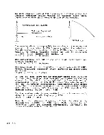
Check to see
that the TPI de voltage drops to
a level
between 0.6 and 1.0 volts.
As long as the de
level stays
between 4.5Vdc for transmit on channel 40 and 0.6 to l.OVdc
for receive on channel 1, the VCO is set properly.
The magnitude of the TPI voltage swing is determined by C216
at the factory.
The optimum value of C216 was
found to be
around 82 pFd.
C216 with a value larger than 82
pFd will
reduce the voltage swing magnitude and vice versa for a
smaller value.
If the lower value drops only
to
1.5Vdc,
then a C216 of 82 pFd should be reduced to
increase the
range.
This should not be necessary when factory supplied
parts are used for D208 (Varactor Diode)
and L201
(VCO
Tuning Coil).
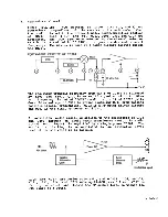
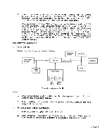
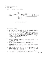
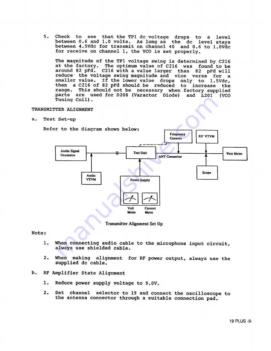
TRANSMITTER ALIGNMENT
a.
Test Set-up
Volt
O rnent
Meter
Meter
Note:
Transmitter Alignment Set Up
1.
When connecting audio cable to the microphone input circuit,
always use shielded cable.
2,
When making alignment for RF power output, always use the
supplied de cable.
b.
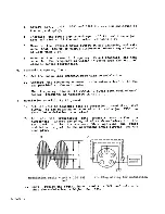
RF Amplifier State Alignment
1.
Reduce power supply voltage to 9.0V.
2.
Set channel selector to 19 and connect the oscilloscope to
the antenna connector through a suitable connection pad.
19 PLUS -9-
Summary of Contents for 19 Plus
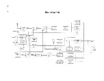
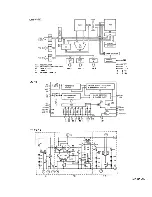
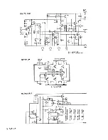
Page 7: ...19 PLUS 6 Block Diagram ...
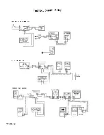
Page 8: ... z smd 61 T X 26 PLL Circuit Block Diagram ...
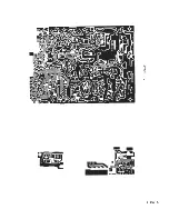
Page 15: ...ß CÛ 19 PLUS 14 ...
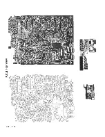
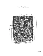
Page 17: ...P C B Bottom View 19 PLUS 16 ...
Page 18: ...401377 с 19 PLUS 17 40I06S ...
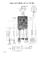
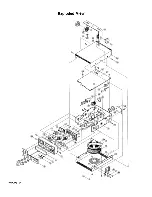
Page 25: ...Exploded View 19 PLUS 24 ...


