Page 15
The pulses produced by the opto receiver are monitored by the circuitry of the motor control PCB.
This control circuit basically monitors for a given number of pulses within a set time frame. Should
this number of pulses decrease beyond the tolerated amount, the supply to the motor is immediately
switched off via a solid-state relay. The control of the motor cut off point may be set by way of a 4
way DIP switch mounted on the motor control board (located in No.1 top sign) thus:
Pole
1 2 Response
off
off
Fastest
on
off
2nd
Fastest
off
on
2nd
Slowest
on
on
Slowest
Pole
3 4 Stop
Resistance
off
off
Weakest
on
off
2nd
Weakest
off
on
2nd
Hardest
on
on
Hardest
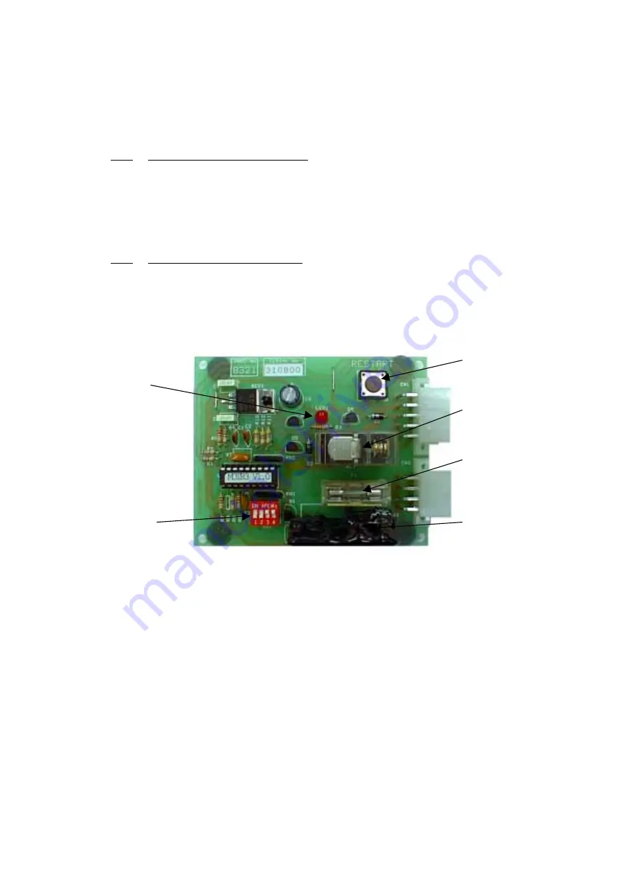
When the system operates and stops the motor, the supply to the motor remains off until manual
reset is initiated. This creates the opportunity to ensure the machine is in a safe state to re-start; a
visual check by the attendant ensuring that there is no longer any item causing the obstruction.
Reset of the system is done by depressing the
'Restart'
switch on the Motor Control PCB or by way
of the remotely located reset switch (mounted in the roof section, behind the end top sign foot
support).
There is an LED on the Motor Control PCB, which indicates the output of the opto-sensor. In
normal operation this will appear to be continuously ON, due to the high repetition rate of the
pulses. This facility may be used to check the operation of the sensors, by manually rotating the
motor shaft and observing the LED. The LED should turn on then off as the hole in the shaft passes
between the sensors. The 20mm fuse on this PCB is to provide over current protection to the solid-
state relay/motor combination. The other relay (RL1) is used to provide a switching function upon
system operation, which is used for signalling to other circuits for alarm operation etc.
Reset
Switch
Alarm/Operation
Relay
Motor
Fuse
Motor Supply
Solid State Relay
DIP Switches
Sensor LED
Summary of Contents for Jacks Hi
Page 21: ...Page 21 9 Electrical Schematic Diagrams ...
Page 28: ......


