6
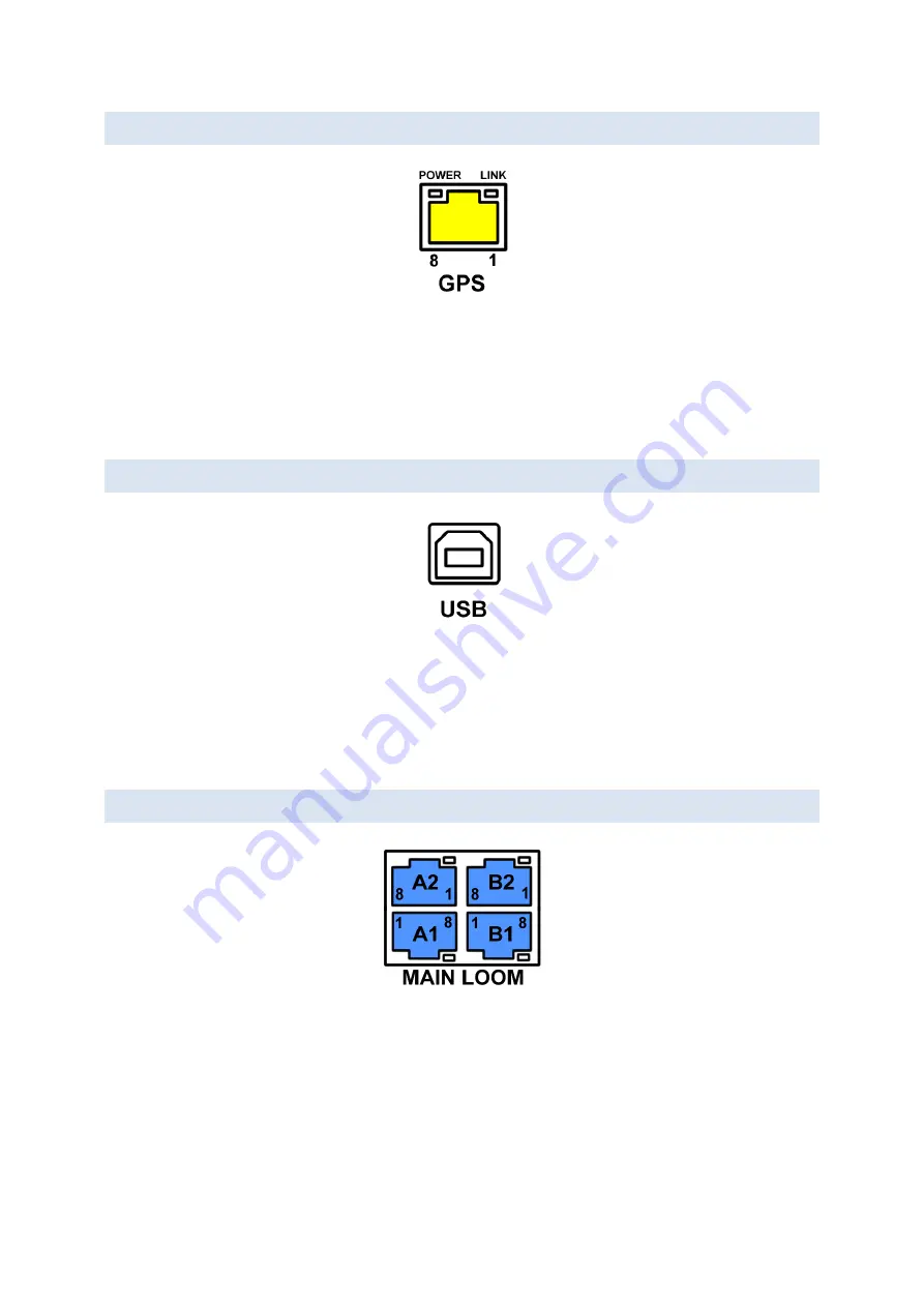
1.4 GPS AERIAL PORT
This is the connection for the GPS ae
rial. The “LINK” indicator will blink once per second when the aerial is
operating correctly. If “LINK” does not blink, then there may be a fault with the aerial or cable. If the “POWER”
indicator goes out when connecting the aerial there is a fault with the aerial. Remove and check aerial cable and
aerial for faults.
•
GPS aerials with a yellow boot on the aerial cable will be compatible with this connection.
1.5 USB PORT
This is the USB connection. When the system is connected via USB cable to a PC, the control panel will display
“USB CONNECTED” and the PC will show the system as a disk drive called “TOURMASTER” within Windows
Explorer.
The USB port is used in conjunction with the coachsound “Route
Builder” software tool to update and
synchronize audio to
ur commentary for the system. (See document: “
Using the Route Builder Tool
”)
1.6 MAIN LOOM PORTS
The “MAIN LOOM” ports are 4 ports that provide power and digital audio to all
hubs and audio controllers in an
installation. “POWER” indicators will light wh
en power is present at each loom port. An indicator that goes out
when a cable is connected indicates that the over-current protection has activated and therefore is a fault on
that loom. Disconnect the loom immediately and test for faults (See document:
“
Coachsound Audio Systems:
Main loom testing and fault finding
”)
Four ports are provided to allow easy installation into both single-deck and double-deck vehicles, as well as for
situations when there are more hubs (audio controllers) that can be run from a single port.


