background image

ZL-GR6150-001-V1

Installation and Connection Instruction Manual

CMA (WUHU) Robotics Company Limited

19

Installation and layout of relevant components on the right side of electric cabinet

Among them, A, B, C, E, F, H and other components have been installed when the cabinet is delivered

from the factory. Only the teaching box, coding cable, power cable (including holding brake),

explosion-proof cable and power supply aviation plug port of the cabinet need to be installed at the

customer's site.

The three-phase four wire system is adopted in the aviation plug port of the power supply of the electric

cabinet to improve the safety performance. The safety devices such as transformer and fuse are connected

with the power module in the control cabinet to supply power to the robot body and related components. The

specific wiring is shown in the figure below.

Summary of Contents for GR Painting Robot Series

Page 1: ...eserved for CMA WUHU Robotics Company Limited For customer use only and any unauthorized use of this manual is strictly prohibited CMA WUHU Robotics Company Limited No 96 East Wanchun Road Jiujiang Ec...

Page 2: ......

Page 3: ...l should be well kept during the life circle of the robot An optional copy can be ordered from CMA if the original one is damaged or lost The address of the new owner is required to be reported to CMA...

Page 4: ...Important Important This warning means special attention should be paid to a certain operation Warnings titled by attention might also lead to severe consequence in different cases Therefore it is str...

Page 5: ...ation and Connection Instruction Manual CMA WUHU Robotics Company Limited manual if the present one is damaged or lost CMA is not responsible for any consequence caused by any unauthorized modificatio...

Page 6: ...d connection of robot body 4 3 1 Requirements for installation site of body 4 3 2 Robot body handling 4 3 2 1 Handling precautions 4 3 2 2 Handling methods 5 3 3 Fixation of robot body 6 3 4 Cable con...

Page 7: ...he cooling fan of the drive 32 4 3 5 Check and replace the dust filter 33 Chapter Five Installation and connection of robot explosion proof cabinet 35 5 1 Precautions for robot explosion protection 35...

Page 8: ......

Page 9: ...nsible for any accident or injury caused by following only one part of this manual The product corresponding to the manual has no fault in the initial state when it leaves the factory and has all safe...

Page 10: ...uitable for handling the specified robot weight If the robot is not installed directly it must be stored according to the robot storage environment requirements Ensure that the expected operating envi...

Page 11: ...1 Set 2 Robot control cabinet cabinetcabinet Standard configuration 1 Set 3 Explosion proof cabinet Standard configuration 1 Set 4 Cable conecting robot body with control cabinet Encoder line 1 Set 5...

Page 12: ...fence and the entrance and exit of safety fence should be equipped with safety lock The flatness of the robot installation plane should be within 0 5mm Ensure that the installation foundation and brac...

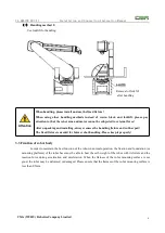
Page 13: ...avoid damage to wiring by operators and forklifts 3 2 2 Handling methods When handling robot the angle of each axis of handling attitude is set as follows 1 Handling method 1 Install 4 M10 lifting rin...

Page 14: ...he handling fixture and rubber pad The fixed fixture is needed for future robot handling Please keep it properly 3 3 Fixation of robot body In order to maintain the best function of the robot in norma...

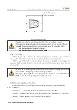
Page 15: ...fixed on the base plate through its four mounting holes with M16 socket head screws the screw length must ensure that the screw length reaches 1 5 times of the nominal diameter of the thread In order...

Page 16: ...than 600mm the connection strength between the support and the ground should be strictly checked to ensure that the connection between the support and the ground is safe and reliable Attention Increas...

Page 17: ...nd control cabinet The cable between the robot body and the control cabinet is mainly composed of two parts power cable including brake cable and encoder cable each of which is a flexible cable Theref...

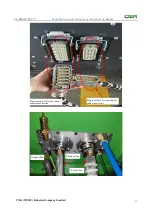
Page 18: ...et The figure below shows the physical diagram of power cable including brake wire and encoder cable aviation plug in terminal of robot control cabinet The left side of the figure is an encoder cable...

Page 19: ...lation and Connection Instruction Manual CMA WUHU Robotics Company Limited 11 Plug in socket of electric control cabinet encoder line Ground line Plug in socket of electric control cabinet power line...

Page 20: ...wn in the figure below on the flange 104 threaded hole on the circumference tighten the fastening screw At the same time use the locating pin and the stop seam in the shaft to position the end tool Fl...

Page 21: ...oad inertia limit Attention When the load at the end of the robot exceeds the rated load capacity the action performance of the robot may deteriorate and the life of the robot will be shortened The sp...

Page 22: ...r arrangement 2 If the plot ratio exceeds 25 or the diameter 12 before operation please consult CMA company 2 Polyester amine is recommended as the material for the internal air pipe Attention The use...

Page 23: ...d accidents caused by this 4 1 Installation requirements of control cabinet 1 Transportation moving electric cabinet for long distance needs to use forklift to lift the electric cabinet away from the...

Page 24: ...net debugging ports and the power supply inlet line aerial plug of the electric cabinet are located on this side 2 In front of the control cabinet is the switch door of the electric cabinet on which t...

Page 25: ...cabinet switch ON OFF B Panel button the maximum button on the upper side is emergency stop button the red button on the left side is alarm indication and the white button on the right side is servo...

Page 26: ...V1 Installation and Connection Instruction Manual CMA WUHU Robotics Company Limited 18 Electric cabinet switch and panel button Installation and layout of relevant components on the left side of elec...

Page 27: ...ng cable power cable including holding brake explosion proof cable and power supply aviation plug port of the cabinet need to be installed at the customer s site The three phase four wire system is ad...

Page 28: ...n described above and will not be introduced here The wiring between the teaching box and the control cabinet is as follows Connect the connector of the teach pendant with the connector of the teach p...

Page 29: ...ZL GR6150 001 V1 Installation and Connection Instruction Manual CMA WUHU Robotics Company Limited 21 Huatu teach pendant...

Page 30: ...are related problems the on site commissioning personnel can adjust or contact the relevant technical personnel of the company according to the electrical schematic diagram delivered with the electri...

Page 31: ...G Safety PLC safety relay contactor H Temperature sensor 1 Fan J Terminal block K Power including brake aviation plug Orange cable coded aviation plug Green blue cable explosion proof aviation plug bl...

Page 32: ...ZL GR6150 001 V1 Installation and Connection Instruction Manual CMA WUHU Robotics Company Limited 24 Detailed wiring and layout in cabinet 2 Detailed wiring and layout in cabinet 3...

Page 33: ...ZL GR6150 001 V1 Installation and Connection Instruction Manual CMA WUHU Robotics Company Limited 25 Detailed wiring and layout in cabinet 4 Detailed wiring and layout in cabinet 5...

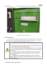
Page 34: ...robot stops and the power is cut off This work must be carried out by properly trained personnel and precautions must be taken to avoid accidental restart and electric shock In case of failure please...

Page 35: ...ddition other non routine maintenance work includes dealing with emergencies such as Sudden breakage Regular maintenance 4 3 1 Replace the fuse The following table gives the code number of fuse fuse c...

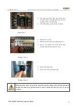
Page 36: ...blown Replace fuse 2 Open the fuse cover Hold the 10x38 fusible core and pull it out Insert a new fusible core 32A of the same model and put on the protective cover Replace fuse 3 Remove the blown fu...

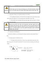
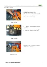
Page 37: ...connection terminal red cable in the figure other colors may also be used Feedback connector blue line Replace drive step 1 Disconnect the terminals at the bottom of all drives Motor cable connection...

Page 38: ...loosen the bolt as shown in the figure Replace drive step 4 Lift the drive pull it out from below and remove it completely Replace drive step 5 Insert the new drive into the old drive slot and hook i...

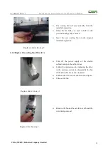
Page 39: ...nnected cables as soon as possible Replace drive step 7 Open the hinge cover and set the address of the drive as shown in the table below Replace drive step 8 4 4 3 Replace the radiator fan Turn off t...

Page 40: ...l installation position Replace radiator fan step 2 4 3 4 Replace the cooling fan of the drive Turn off the power supply of the electric cabinet and open the cabinet door Follow the instructions for r...

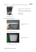
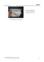
Page 41: ...ce you remove the old fan replace it with a new one and re connect the power cord in the drive Reposition the fan Review the drive Replace driver fan step 3 4 3 5 Check and replace the dust filter Rem...

Page 42: ...1 Installation and Connection Instruction Manual CMA WUHU Robotics Company Limited 34 If the filter accumulates too much dust replace it in time Install the protective grille Check and replace the dus...

Page 43: ...idance or supervision of professional and technical personnel it is not allowed to loosen the fastening screw of pressurization chamber 2 When the robot has been powered on do not open the shell of th...

Page 44: ...2 Introduction to the interior of explosion proof cabinet 1 power supply module 2 Safety PLC safety relay Pilz safety PLC Phoenix safety relay 3 explosion proof barrier 4 air pressure regulating valv...

Page 45: ...blems If there are any related problems the on site commissioning personnel can adjust or contact relevant technical personnel of CMA according to the electrical schematic diagram delivered with the e...

Page 46: ...o parts the first part is the air inlet interface connected with the gas supply pipeline and the second part is the air outlet interface connected with the robot body The real object is shown in the f...

Page 47: ...connected with 3 reserved air pipes of robot body The three outlet ports of explosion proof cabinet are numbered A B and C respectively corresponding to the three reserved gas pipe ports on the robot...

Page 48: ...ligent Equipment Co Ltd No 96 East Wanchun Road Jiujiang Economic Development District Wuhu Anhui Province www efort com cn Service Hotline 400 052 8877 CMA Wuhu Robotics Co Ltd No 96 East Wanchun Roa...

Reviews: