16
Motor Component Testing and Inspection
MOTOR
1
2
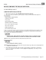
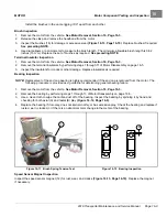
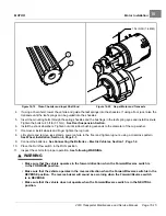
Figure 16-10
Armature Test
MOTOR FRAME AND FIELD WINDINGS INSPECTION
1.
Remove the motor from the vehicle.
See Motor Removal, Section 16, Page 16-3.
2.
Remove the end cap and armature by performing steps 1 through 6 of Motor Disassembly on page 16-5.
3.
Burned or scorched insulation on the field windings indicates the motor has overheated due to overloads or
grounded or shorted coil windings. If the insulation on the field windings is scorched, replace the motor or
the stator shell assembly.
MOTOR BRUSH, SPRING, AND TERMINAL INSULATOR INSPECTION
Brush Spring Tension Test
1.
Remove the motor from the vehicle.
See Motor Removal, Section 16, Page 16-3.
2.
Release the clasp and remove the headband from the motor.
3.
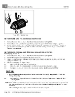
Inspect the brush springs (18)
. Replace springs that are discolored from heat
(light gold or blue tinted).
4.
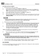
Test the brush springs for proper tension.
4.1.
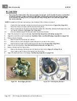
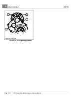
Place a C-shaped steel plate (1) on a scale (2).
4.2.
Place the end of the C-shaped plate (1) so that it is between the spring and the brush.
4.3.
Gently pull the scale (2) to obtain the spring tension reading.
See following CAUTION.
CAUTION
• When checking brush spring tension, do not over-extend the spring. Using excessive force will
damage the spring.
4.4.
Replace springs which require a force of less than 35 ozf. (990 gf.)
.
See
following NOTE.
NOTE:
When installing new brushes, remove and replace brushes one at a time. This method ensures the terminals
and brushes will be properly positioned in the rigging. Refer to
for brush
installation.
When replacing brushes, replace all four brushes. Never replace only two.
Page 16-8
2019 Transporter Maintenance and Service Manual
Summary of Contents for TransPorter 4
Page 2: ......
Page 271: ...ELECTRIC MAIN HARNESS Wiring Diagrams Electric Main Harness 18 ...
Page 272: ... Page intentionally left blank ...
Page 273: ...ELECTRIC INSTRUMENT PANEL HARNESS Wiring Diagrams Electric Instrument Panel Harness 18 ...
Page 274: ... Page intentionally left blank ...
Page 275: ...ELECTRIC ACCESSORIES HARNESS Wiring Diagrams Electric Accessories Harness 18 ...
Page 276: ... Page intentionally left blank ...
Page 282: ...NOTES ...
Page 283: ...NOTES ...
Page 284: ...NOTES ...
Page 285: ......
Page 286: ......

