MOTOR
Motor Disassembly
16
MOTOR DISASSEMBLY
1.
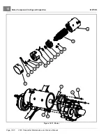
Release the clasp and remove the headband assembly (21) from the motor. Visually inspect brushes and
springs.
2.
Before continuing disassembly, place match marks on the motor end cap (20) and motor frame (14).
3.
Remove speed sensor (10) and magnet (12).
3.1.
Remove the two screws (11) and clamp that secure the speed sensor (10) to the end cap (20).
3.2.
Remove the bolt (13) securing the magnet (12) to the armature shaft (15). Hold the back of the armature
assembly to keep it from turning as you remove the bolt.
3.3.
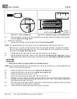
Inspect the speed sensor magnet.
See Speed Sensor Magnet Inspection on page 16-9.
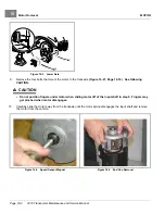
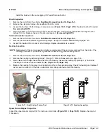
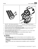
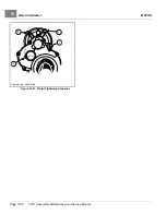
Figure 16-6
Brush Springs Positioning
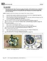
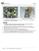
Figure 16-7
Armature Removal
4.
Orient the motor so that the splined end of the armature is facing down.
5.
Remove the four end cap bolts. The weight of the motor housing will cause it to drop when the bolts are removed.
See following CAUTION.
CAUTION
• The motor housing will drop when the bolts are removed. Do not put fingers under the motor housing
when removing bolts.
6.
Remove the end cap and armature from the motor frame
.
7.
Inspect the brush springs for proper tension.
See Motor Brush, Spring, and Terminal Insulator Inspection on
8.
Remove the armature from the end cap bearing.
See following CAUTION and NOTE.
2019 Transporter Maintenance and Service Manual
Page 16-5
Summary of Contents for TransPorter 4
Page 2: ......
Page 271: ...ELECTRIC MAIN HARNESS Wiring Diagrams Electric Main Harness 18 ...
Page 272: ... Page intentionally left blank ...
Page 273: ...ELECTRIC INSTRUMENT PANEL HARNESS Wiring Diagrams Electric Instrument Panel Harness 18 ...
Page 274: ... Page intentionally left blank ...
Page 275: ...ELECTRIC ACCESSORIES HARNESS Wiring Diagrams Electric Accessories Harness 18 ...
Page 276: ... Page intentionally left blank ...
Page 282: ...NOTES ...
Page 283: ...NOTES ...
Page 284: ...NOTES ...
Page 285: ......
Page 286: ......


