


19
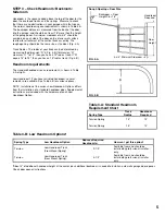
STEP 11 – Assembling and Installing
the Vertical Track
Before assembling brackets to vertical track be sure to read
Step 11-1 and Step 11-2. Refer to illustration for placement of
brackets on track.
NOTE:
Brackets may already be riveted in place. If additional
adjustment is required, the rivets can be drilled out and the
brackets can be reattached with track bolts and flange nuts
(available through the toll-free Consumer Services number, see
outside cover).
To avoid installation problems that could result in injury or
property damage, use only track provided with new door.
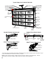
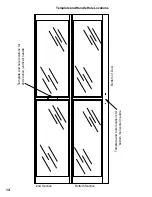
Step 11-1:
Loosely fasten the track brackets to the vertical
track using one 1/4" x 5/8" track bolt and 1/4" flange nut as
shown with the head of the bolt inside the track. There are
two sizes of brackets for 7’ high doors, and three sizes for 8’
high doors. The shortest track brackets should be installed ten
inches from the bottom of the track with the flange facing the
flat side of the track, one on the left and one on the right. The
next larger sized pair of brackets should be installed centered
on the track. If you have an 8’ high door, the remaining pair
of brackets should be installed ten inches from the top of the
vertical track. The flat side of the track goes toward the wall.
(FIG. 11-A)
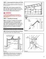
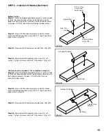
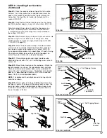
Step 11-2:
Loosely attach the flag bracket to the top of the
track with two 1/4" x 5/8" track bolts and 1/4" flange nuts with
the head of the bolts in the track. Make sure to place bolts and
nuts in correct holes (FIG. 11-B, See FIG. 11-C for bracket
placement).
(Refer to FIG. 11-B to determine proper bolt placement.)
NOTE:
If additional adjustment is required, horizontal slots in
flag brackets can be used for attachment to vertical track.
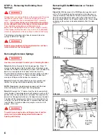
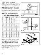
Step 11-3:
Place the track over the rollers on the door. Move
the track close to the door so that the rollers are all the way
into the hinges. Do not force the track too tightly or the door
will bind. This should leave about 1/2" between the edge of the
door and the track. Pilot holes of 3/16" are required at each
lag screw location before installing the lag screw. Lift track
about 1/2" from the floor and fasten the flag bracket and track
brackets to the jamb with 5/16" x 1-5/8" lag screws. The flag
bracket requires three screws, one each in the top, middle, and
bottom holes. Do this for both sides of the door. When the track
brackets and flag brackets are securely fastened to the jamb,
tighten the track bolts and flange nuts connecting the flag
brackets to the tracks. (FIG. 11-D)
NOTE:
The tops of the vertical tracks must be level with
each other. Check this by measuring from the top of the door
sections to the top of the track on both sides. If they are not
equal, cut some material off the bottom of one track to lower it
or raise the other track.
Do not raise the vertical track beyond the bottom rollers
on the bottom section of door.
NOTE:
Do not attach any brackets directly to drywall. All track
brackets, flag brackets, and spring brackets should only be
attached directly to wood jams.
FIG. 11-A
FIG. 11-B
FIG. 11-C
FIG. 11-D
1/4" Flange
Nut
1/4" x 5/8”
Track Bolt
Wall
Side
Top View
Left Side
Note: Use One
Track Bolt In Slot
1/4" Flange Nut
Use These
Two Holes
1/4" x 5/8”
Track Bolt
Top
Bottom
Shorter
Track
Bracket
Right Hand
Vertical
Track
Assembly
Longer
Track
Bracket
Flag Bracket
Left Hand
Vertical Track
Assembly


