


36
2.1
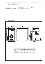
LOCAL CHAUDIÈRE
Le local chaudière doit être conforme à
toutes les prescriptions requises par les
normes en vigueur.
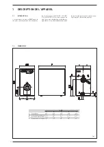
2.2
DI MEN SIO NS DU LOCAL CHAUDIÈRE
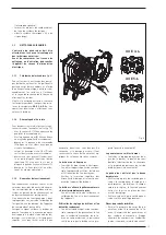
Placer le corps de la chaudière sur un
socle d’au moins 10 cm de haut qui aura
été préparé.
Le corps de la chaudière doit reposer sur
une surface permettant de le faire glis-
ser en utilisant de préférence des tôles
en fer. Il faut laisser un espace minimum
de 0,60 m entre les parois du local et la
chaudière et au moins 1 m entre la par-
tie supérieure de l’enceinte et le plafond,
réductible à 0,50 m pour les chaudières à
chauffe-eau incorporé (la hauteur mini-
mum du local doit dans tous les cas être
égale ou supérieure à 2,5 m).
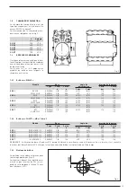
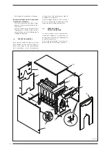
2.3
RACCORDEMENT DE L’ÉQUIPEMENT
En effectuant les raccordements hydrau-
liques, veiller à ce que soient respectées
les indications fournies sur la fig.1.
Il est opportun que les raccordements
soient facilement déconnectables au
moyen d’embouts à raccords pivotants.
L’équipement doit être du type à vase
d'expansion fermé.
2.3.1 Remplissage de l’équipement
Avant de brancher la chaudière, il est bon
de faire circuler de l’eau dans les tuyaux
pour éventuellement éliminer les corps
étrangers susceptibles de compromettre
le bon fonctionnement de l’appareil.
Effectuer le remplissage très lente-
ment pour permettre aux bulles d’air de
s’échapper par les évents opportuns ins-
tallés sur le système de chauffage.
Dans les systèmes de chauffage en
circuit fermé, la pression de charge-
ment à froid du système et la pression
de pré-gonflage du vase d'expansion
doivent correspondre ou tout au moins
être égales ou supérieures à la hauteur
de la colonne statique de l'installation
(par exemple, pour une colonne statique
5 m, la pression de pré-gonflage du vase
et la pression de chargement du système
doivent au moins correspondre à la va-
leur minimale de 0,5 bar).
2.3.2 Caractéristiques de l’eau
d’alimentation
Afin d’éviter les incrustations ou les
dépôts sur l’échangeur principal, l’eau
d’alimentation du circuit de chauffage
doit être traitée conformément à la
norme UNI-CTI 8065. Il est absolument
indispensable de traiter l’eau dans les
cas suivants :
– Systèmes très étendus (contenant de
grosses quantités d’eau)
– Émissions fréquentes d'eau d'appoint
dans le système.
– S’il faut entièrement ou partiellement
vider le système.
2.4
RACCORDEMENT AU
CONDUIT DE FUMÉE
Le conduit de fumée revêt une impor-
tance fondamentale pour le fonction-
nement de l’installation. En effet, sa
réalisation sans respecter les critères
opportuns risque d’entraîner un dysfonc-
tionnement du brûleur, une augmenta-
tion de la nuisance sonore, la formation
de rouille, de la condensation et des
incrustations. Le conduit de fumée doit
donc être conforme aux prescriptions
suivantes :
– il doit être réalisé dans un matériau
imperméable et résistant à la tempé-
rature des fumées et des condensats ;
– il doit posséder une résistance méca-
nique suffisante et une faible conducti-
vité de la chaleur ;
– il doit être parfaitement étanche pour
éviter que le conduit de fumée en
question ne refroidisse ;
– il doit être le plus vertical possible et
sa partie terminale doit posséder un
aspirateur statique qui assure une
évacuation efficace et constante des
produits de la combustion ;
– afin d'empêcher le vent de créer des
zones de pression autour du faîte, de
nature à dépasser la force ascendante
des gaz brûlés, il est nécessaire que
l’orifice d’évacuation dépasse d'au
moins 0,4 m toute structure adjacente
à la cheminée même (y compris le
sommet du toit) à moins de 8 m ;
– le diamètre du conduit de fumée doit
être égal ou supérieur à celui du rac-
cord de la chaudière : pour les conduits
de cheminée à section carrée ou rec-
tangulaire, la section interne doit être
augmentée de 10 % par rapport à celle
du raccord de la chaudière ;
– il est possible de déduire la section
utile du conduit de fumée de l’équation
suivante :
S se ction ré sul tan te en cm
2
K coefficient en réduction :
– 0,045 pour le bois
– 0,030 pour le charbon
– 0,024 pour le gasoil
– 0,016 pour le gaz
P puissance de la chaudière en kcal/h
H hauteur de la cheminée, en
mètres, mesurée de l’axe de la
flamme à l’évacuation de la che-
minée dans l’atmosphère. En di-
mensionnant le conduit de fumée,
il faut tenir compte de la hauteur
réelle de la cheminée en mètres,
mesurée de l’axe de la flamme au
sommet et réduite de :
– 0,50 m par changement de di-
rection du conduit de raccord
entre la chaudière et le conduit
de fumée ;
– 1,00 m par mètre de développe-
ment horizontal du raccord en
question.
2.5
BRANCHEMEN T ÉLECTRIQUE
La chaudière, qui est dotée d’un câble
électrique d’alimentation, doit être ali-
mentée avec une tension monophasée
230V - 50Hz au moyen d’un interrup-
teur général protégé par des fusibles.
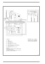
Le câble du régulateur climatique, dont
l’installation est obligatoire pour obtenir
une meilleure régulation de la tempéra-
ture ambiante, doit être raccordé comme
indiqué sur la fig. 6. Brancher ensuite le
câble d’alimentation du brûleur et celui
de la pompe de circulation du système
fournis en équipement.
REMARQUE : L'appareil doit être bran-
ché à une installation efficace de mise
à la terre. L’entreprise CLIMIT décline
toute responsabilité en cas de dom-
mages corporels dus au défaut de mise
à la terre de la chaudière. Avant d’ef-
fectuer toute opération sur le tableau
électrique, débrancher l’alimentation
électrique.
P
S = K
√
H
2 INSTALLATION
Summary of Contents for GG E 3
Page 1: ...GG E 3 7 Cod 6276052A 07 2019 IT ES ENG FR RUS ...
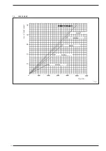
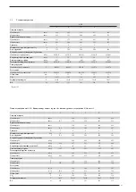
Page 5: ...3 1 4 PERDITE DI CARICO CIRCUITO CALDAIA Fig 2 GG E 7 GG E 6 GG E 5 GG E 4 GG E 3 ...
Page 12: ...10 NOTE ...
Page 26: ...24 1 4 LOSS OF HEAD Fig 2 Loss of head mbar Flow l h GG E 7 GG E 6 GG E 5 GG E 4 GG E 3 ...
Page 36: ...24 1 4 LOSS OF HEAD Fig 2 Loss of head mbar Flow l h GG E 7 GG E 6 GG E 5 GG E 4 GG E 3 ...
Page 63: ...51 NOTE ...
Page 64: ...52 NOTE ...
Page 65: ......
Page 66: ...Via Garbo 27 37045 Legnago Vr Tel 39 0442 631111 Fax 39 0442 631292 ...