background image

1.0 Safety information

General safety notes

Carefully read the operating manual 
before placing the unit in service 
for the first time. It contains useful 
tips and notes as well as hazard 
warnings to prevent injury or 
material damage. Failure to follow 
the directions in this Manual can 
endanger persons, the environment 
and the equipment itself and will 
void any claims for liability.


Keep this operating manual and 
the refrigerant data sheet near to 
the units.


Only qualified personnel may 
set up and install the units and 
components.


The set-up, connection and 
operation of the units and its 
components must be undertaken 
in accordance with the usage and 
operating conditions stipulated 
in this manual and comply 
with all applicable regional 
regulations. 


Mobile units must be set up 
securely on suitable surfaces and 
in an upright position. Stationary 
units must be permanently 
installed for operation.


Modification of the units and 
components supplied by CLIMIA 
is not permitted and can cause 
malfunctions.


The units and components 
should not be operated in areas 
where there is an increased risk of 
damage. Observe the minimum 
clearances.


The electrical power supply 
should be adapted to the 
requirements of the units.


The operational safety of the 
units and components is only 
assured providing they are 
used as intended and in a 
fully assembled state. Safety 
devices may not be modified or 
bypassed.


Do not operate units or 
components with obvious 
defects or signs of damage.


All housing parts and unit 
openings, e.g. air inlets and 
outlets, must be free from foreign 
objects, liquids and gases. 


The units and components must 
be kept at an adequate distance 
from flammable, explosive, 
combustible, abrasive and dirty 
areas or atmospheres.


Contact with equipment parts or 
components can lead to burns or 
injury. 


Installation, repair and 
maintenance work may only 
be carried out by authorised 
specialists. Visual inspections and 
cleaning can be performed by 
the operator as long as the unit is 
disconnected from the power.


Appropriate hazard prevention 
measures must be taken to 
prevent risks to people when 
performing installation, repair, 
maintenance or cleaning work on 
the units.


The units and components
should not be exposed to any 
mechanical load, extreme levels 
of humidity or direct exposure to 
sunlight. 

Safety instructions for the  

operator

  The units and components must 

not be exposed to any mechanical 
load, extreme levels of humidity or 
extreme temperatures.  Operation 
in rooms with possible ignition 
sources (e.g. open flames, gas 
heaters, electric heaters) is also 
prohibited.

  During operation of the unit, icing 

of the heat exchangers may occur 
occasionally. The units feature an 
automatic defrosting function 
if required. Never thaw the heat 
exchangers independently!

  The refrigerant R290 used in the 

unit is highly flammable, invisible 
and odourless. It is imperative 
that the safety instructions in 
the installation and operating 
instructions are observed.

  The unit may only be stored and 

operated in rooms larger than 8 
m².

  Possible regional laws and 

regulations must be observed.

  Air intake and outlet areas must 

be kept clear. Never cover the unit.

  The unit must be stored in such a 

way that mechanical damage can 
be ruled out. The storage location 
must be sufficiently large and well 
ventilated.

Warning of inflammable 

substances

CLIMIA

4

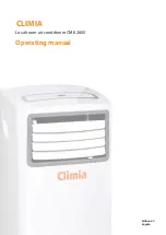
Summary of Contents for CMK 2600

Page 1: ...Edition 3 0 English CLIMIA Local room air conditioner CMK 2600 Operating manual ...

Page 2: ...CLIMIA ...

Page 3: ...rors or misprints 1 0 Safety information 4 5 2 0 Environmental protection and recycling 5 3 0 Guarantee 5 4 0 Intended use 5 5 0 Transportation and packaging 6 6 0 Unit description 6 7 0 Operation 7 8 8 0 Before commissioning 9 10 9 0 Commissioning 10 10 0 Shutdown 10 11 11 0 Filter cleaning 11 12 0 Care and maintenance 11 13 0 Installation scheme for wall pass through 12 14 0 Troubleshooting and ...

Page 4: ... objects liquids and gases The units and components must be kept at an adequate distance from flammable explosive combustible abrasive and dirty areas or atmospheres Contact with equipment parts or components can lead to burns or injury Installation repair and maintenance work may only be carried out by authorised specialists Visual inspections and cleaning can be performed by the operator as long...

Page 5: ...f any kind may only be carried out by certified specialist personnel Intervention in the refrigeration circuit by personnel who are neither certified nor authorised by the manufacturer is strictly prohibited The prerequisite for personnel being qualified is knowledge of handling flammable refrigerants National regulations for the transport of equipment must be observed Safety relevant device stick...

Page 6: ...r by means of the flexible exhaust air hose The condensate arising during cooling mode is continually drained off via the condenser by means of a condensate pump located in the unit the condenser evaporates the condensate and discharges it to the outside via the exhaust air hose The unit filters and dehumidifies the air thereby creating a comfortable room climate It works fully automatically and o...

Page 7: ...ncreases by 1 C after 30 minutes After another 30 minutes the setpoint increases by a further 1 C and then remains at this setting for 7 hours before returning to the original temperature setpoint LED Display display lighting key only on the remote control Switches the display and the unit LED on or off Green LED operating mode indicator on the LCD Indicates the active operating mode of the unit F...

Page 8: ...uenced The unit display shows the actual current temperature Timer With the timer function of the IR remote control the unit can be switched on or off with a time delay Automatic switch off 1 Switch the unit on with the On Off key 2 The Timer OFF key on the IR remote control enables the desired time delay for unit switch off to be set in 0 5 hour steps After successful programming the timer indica...

Page 9: ...n with the discharge side pointing into the room When positioning observe the following notes After unpacking the unit let it sit on its transport rollers for at least 5 minutes before you switch it on Set the unit down in a stable position on a level and firm floor If the floor is uneven then this can lead to vibrations and disturbing noises Check whether the stopper in the condensate drain is pr...

Page 10: ...e surfaces of the evaporator fins This will transport the remaining moisture out of the unit and this will avoid unpleasant odours when the unit is re commissioned 2 Switch the unit off with the On Off key pull out the power plug and wind up the power supply cable Ensure that the cable is not kinked or too severely bent 3 Place a suitable container underneath the condensate drain of the internal r...

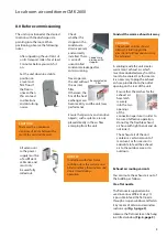
Page 11: ...nance contract with an appropriate specialist firm This will guarantee that your equipment always operates reliably 11 0 Filter cleaning The unit is equipped with an air filter This can be withdrawn from the rear of the unit The filter must be cleaned at regular intervals Clean the air filter at intervals of no more than 100 operating hours Reduce this interval in the case of heavily contaminated ...

Page 12: ...ion material 3 Brick the slide tube into the core hole such that it sits flush on both sides of the wall 4 Fasten the protection grid on the outside of the wall with 4 screws Take rain ingress into account when fitting the grid 5 Insert the interior flap valve and fasten this likewise with 4 screws The Top legend on the flap valve must be visible from the inside 6 When shutting down the unit e g b...

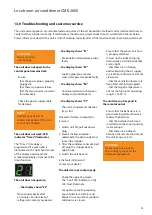
Page 13: ... Check the operating mode The Cool LED indicator on the LCD must illuminate For optimum cooling capacity you should close curtains and blinds Also ensure that windows and doors are closed Ensure that the exhaust air hose is properly attached It must not be kinked sloping downwards or laid in bends that are too tight that there are no foreign bodies impairing the air supply or air exhaust observe m...

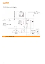
Page 14: ...15 0 Electrical wiring diagram Fig 12 Connection diagram CMK 2600 CLIMIA 14 ...

Page 15: ...Local room air conditioner CMK 2600 16 0 Unit illustration 1 2 3 4 5 6 7 8 9 10 11 12 13 14 15 16 17 18 19 20 21 22 23 24 25 Fig 13 Exploded view of unit CMK 2600 15 ...

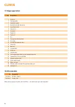
Page 16: ...lter grille 15 Back wall 16 Display board 17 Unit cover 18 Control board 19 Suction pipe pipe contact sensor temperature probe 20 Temperature sensor recirculation 21 Infrared remote control 22 Unit connection port 23 Exhaust air hose 24 Window nozzle wall pass through connection port 25 Sealing cover 18 0 Accessories No Designation Not shown Wall pass though Not shown Window seal CLIMIA 16 When or...

Page 17: ...to 35 35 to 65 Refrigerant R290 Max operating pressure cooling cycle kPa 4200 1500 Refrigerant basic quantity kg 0 15 Refrigerant CO2 equivalent t 0 00 Recirculation air volume flow min max m h 194 286 Sound pressure level min max 2 dB A 47 53 Sound power level max dB A 62 Power supply V Ph Hz 230 50 Enclosure class IP X0 Electr rated power consumption 1 kW 0 90 Electr rated current consumption 1 ...

Page 18: ...hnik Niemeierstraße 13 D 32758 Detmold Equipment machinery variant Local room air conditioner Series Class CLIMIA CMK 2600 Series Class Number 1897 Applicable provisions EU Directives The aforementioned products comply with the following EU directives 2014 35 EU Low Voltage Directive 2014 30 EU Electromagnetic Compatibility 206 2012 for implementing directive 2009 125 EU 626 2011 for implementing ...

Page 19: ......

Page 20: ...Intakt GmbH Climia Klima und Wärmetechnik Niemeierstraße 13 D 32758 Detmold ...

Reviews: