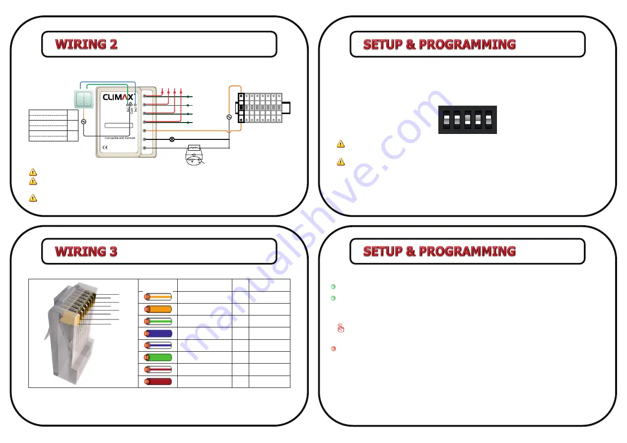
Ch1
Ch2
L
B
A
-
+
Power In: 18-24V DC
50mA max
CL-AB-5AMR2-HV
2X5A Micro Relay
To Next Module
From Previous
Module
Inducv e Load
47
1/2 W
F
0.1
Snubber
MOV
N
L
MODE
Circut
Breaker
MODE
Circut
Breaker
MODE
Circut
Breaker
MODE
Circut
Breaker
MODE
Circut
Breaker
MODE
Circut
Breaker
MODE
Circut
Breaker
MODE
Circut
Breaker
N
L
CL-AB- 5AMR2-HV
240V
CL-AB- 5AMR2-HVLC
110V
5-24V
CL-AB- 5AMR2-MV
CL-AB- 5AMR2-MVLC
CL-AB- 5AMR2-LV
CL-AB- 5AMR2-LVLC
1
2
3
4
5
6
7 8
Color
Color Name
Pin
C-Bus
Orange/White
Orange
Green/White
Blue
Blue/White
Green
Brown/White
Brown
1
2
3
4
5
6
7
8
A(DATA+)
B(DATA-)
TXD*
RXD*
GND
GND
VCC
VCC
Change Module Address
The module address can be set from 0 to 31 by means of a dip switch called “address selector
switch”. Before changing module address the main power must be disconnected. The address must
be defined in binary. For instance to set address “19”, the dip switch must be as below:
Never set the address “0” and “1” as “0” is not valid in C-Bus protocol and “1” is always
dedicated for
RS-232 GatewayPro
module.
Check all C-Bus module addresses to avoid repev e address allocaon.
Channel Toggling
Each channel can be toggled by connecng /disconnecng COM to corresponding input on control
pins.
Follow the diagram below in order to apply appropriate input/output and connect modules with
listed part numbers to C-Bus network.
Use following instrucon to connect the module to C-Bus network with Cat6 cable.
* TXD & RXD are generally applicable for modules which are working in direct mode. for this
product TXD & RXD will be used in C-Bus networks with long cables, for GND & VCC respecv ely in
order to lower voltage drop.
5
7
6
8
Before wiring the device, always unplug the main power.
Before adding a new module to C-Bus network, ensure the previous module has a valid
address and is working properly.
In case of using capaciv e or inducv e loads, permissible current is less than normal mode
(resisv e load) depending on load condion.
Module’s LEDs
Power:
When the module is connected to main power, “Power LED” will flash smoothly.
Status:
When the module is connected to C-Bus network and receives valid data packets,
“Status LED” flashes quickly. “Status LED” is “off” when the module doesn’t receive any data.
When the module is receiving invalid data packet ,”Status LED” will remain “on” for 5 seconds.
In some cases, when a new module is added to C-Bus network,
“Status LED” might remain
“on”
for 5 seconds. This situa on must not be considered as an error.
Ch1 and Ch2:
Shows the status of module’s relays.
ON
1
2
3
4
5


