background image

®

www.climacoolcorp.com

22

Chilled Water Temperature

Modules are designed for a leaving water temperature 

range from 40°F to 62°F . All cataloged modules can operate 

safely in this range without the need of special controls or 

glycol additives . Leaving water temperatures below 40°F 

can result in evaporator suction temperatures below the 

freezing point of water . Therefore, a glycol solution additive 

is required that will protect the evaporator from freeze ups 

at lower operating suction temperatures . The full range of 

leaving chiller fluid using glycol is 20°F to 62°F. 

Condenser Water Temperature

The condensers are designed to operate most efficiently 

at lower entering water temperatures for lower power 

consumption . The expansion valve, however, relies on 

the pressure difference across the valve to drive the liquid 

refrigerant through . It is necessary to maintain a minimum 

pressure differential across the thermal expansion valve 

(equivalent to a 30°F difference between saturated 

liquid temperature in the condenser and saturated vapor 

temperature in the evaporator) to avoid loss of efficiency 

and system performance. This pressure differential is most 

commonly ensured by cycling the fans on the cooling tower 

to maintain the entering condenser water temperature 

above the minimum temperature of 60°F . An alternate 

method to maintain the minimum entering condenser water 

temperature above 60°F is to employ a bypass arrangement 

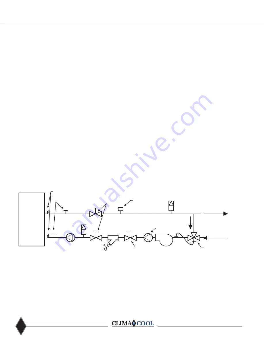
as shown in Figure 24 below . This valve is an automatic 

3-way bypass valve, which senses the temperature of the 

mixed water entering the condenser . If this mixed water 

temperature falls below 60°F the valve will re-circulate 

the leaving condenser water and mix it into the entering 

condenser water stream (bypassing the cooling tower).  

The full range of entering condenser water is 60°F to 95°F 

for standard applications and maximum leaving hot water 

temperature of 135°F for high temperature applications . 

For entering water less than 60°F refer to Motorized Water 

Isolation Valves under Options and Accessories on page 41 .

Figure 24 - Condenser Water System

Note: Only required for equipment without motorized condenser valves. 

Pressure Taps

Thermometer 

Wells

Isolation Valves

Condenser Water 

Flow Sensor or 

Switch

Pressure Relief Valve

Flow to Tower Load

Flow from Tower 

Cooling Tower 

Bypass Valve

Strainer Isolation 

Valve

Pump

Backflow 

Preventer

Strainer

Drain 

Valve

Backflow 

Preventer

Pressure 

Relief Valve

Water Temperature Requirements

Summary of Contents for UCH 30

Page 1: ...Water Cooled Ultimate Chiller Solution Model UCW H 30 50 70 85 Installation Operation Maintenance Manual ...

Page 2: ...orator Water Pressure Drop Charts 23 Glycol Performance Adjustment Factors Charts 24 25 Pre Startup 26 Pre Startup Check List 27 Startup 28 29 Superheat Subcooling Flowchart 30 Startup and Warranty Form 31 Chiller Operation and Maintenance 32 Heat Exchangers 33 Cleaning Arrangment 34 Operational Limitations 35 Compressor Information 36 Refrigeration Circuit Diagram 37 38 Refrigeration System Re Pr...

Page 3: ...T WATER AND REFRIGERANT SYSTEMS UNDER PRESSURE Isolate Lockout source and relieve pressure BEFORE servicing equipment Failure to relieve pressure may result in property damage serious bodily injury or death EAU ET FRIGORIGÈNE EQUIPEMENTS SOUS PRESSION Isoler la source de verrouillage et de soulager la pression avant entretien de l équi pement Le défaut de soulager la pression peut entraîner des do...

Page 4: ... header grooved couplings and mounting hardware kits are on site prior to connecting the modules Note Consult factory for handling other than in the upright position Rigging and Lifting Each module should be lifted using a pallet jack or fork lift If it is necessary to utilize a crane for rigging or lifting each module shall be lifted using lifting straps and spreader bars using rigging points ide...

Page 5: ...er fluid connections are 6 grooved coupling for the 30 50 and 70 ton modules The 85 ton module uses 8 grooved couplings Model UCW H Module and Compressor 30 50 70 85 Capacity tons 31 7 51 5 67 2 82 8 kW Ton 0 738 0 746 0 744 0 740 Full Load EER 2 16 3 16 1 16 1 16 2 Refrigerant Circuits quantity 2 2 2 2 Compressor Type Scroll Scroll Scroll Scroll Compressor Quantity 2 2 2 2 Compressor Nominal Hp p...

Page 6: ... Width in B Unit Height in C Header Width in D Unit Depth in E Header Location F Header Location G Header Location H Header Location I Header Location J Header Location K Header Location Header Connection in 1 030 208 230 460 575 3 60 34 65 1 8 34 1 4 55 1 2 41 1 4 27 1 2 19 9 1 4 58 58 47 1 2 6 050 208 230 460 575 3 60 34 65 1 8 34 1 4 55 1 2 41 1 4 27 1 2 19 9 1 4 58 58 47 1 2 6 070 208 230 460 ...

Page 7: ...e may occur Figure 1 Figure 2 Lifting Strap Lifting Strap Spreader Bar Spreader Bar Spreader Bar Figure 1 Figure 2 Figure 3 Lifting and Transporting Modules Pallet jacks or forklifts are required for lifting and transporting the module Each module has base cutouts provided for ease of maneuverability 60 forks are recommended to prevent damage to chiller base Rigging and Lifting Procedures ...

Page 8: ...ing isolators or pads is not required Should isolators or pads be desired install in accordance with Figures 4 and 5 Figure 4 Spring Vibration Isolators Option 4 Rail Minimum Recommended by others Spring Vibration Isolators by others 4 Rail Minimum Recommended by others 4 Rail Minimum Recommended by others Spring Vibration Isolators by others 4 Rail Minimum Recommended by others Note Size and weig...

Page 9: ...com Mounting Holes Top View of UC 085 Base Pan Shown Front of Unit 33 675 The six mounting hole locations are circled in red Dimensions are shown in inches Top View of UC 030 050 and 700 Base Pan Shown Front of Unit 33 675 ...

Page 10: ...ess to modules 2 Allow a minimum of 18 height clearance for 30 50 and 70 ton modules Allow a minimum of 24 height clearance for 85 ton modules 3 Local building and or electrical codes may require additional clearance Consult applicable codes CoolLogic Control Panel Wall Mounted Top View Rear Service Access Front Service Access 36 36 30 30 12 ...

Page 11: ...Manual Valves Motorized Condenser Valves Voltage E Evaporator Motorized Valves Manual Condenser Valves F 460 3 60 less Manual Condenser Valves for Air Cooled H 208 230 3 60 M Manual Valves for Evap Condsr N 575 03 60 less Manual Condenser Valves for Air Cooled U 380 3 50 X Special Options Application Controls Electrical C Cooling A Standard Controls H Heat Recovery S Single Module Controls R Rever...

Page 12: ...nit base pan First module should be set set adjacent unit on mounting surface roughly aligned 1 inches away from the first unit While holding spacer in place work through first modules front base cutout to place a washer and insert bolt through front mounting hole and spacer Repeat the process for the rear mounting hole Line up mounting hole of adjacent module with bolt from previous module and wo...

Page 13: ...he pipe to eliminate any damage to the gasket With gasket in place on each header of the positioned unit see Figure 11 move the second module into position and line up the piping Ensure alignment is maintained for any additional modules to be added Sound Attenuation Panels and Gasket Attenuation panels are enclosures made of 18 gauge galvanized steel with powder coat paint finish and fiberglass in...

Page 14: ...ther pipe end Place coupling halves over the gasket and make sure that the coupling keys the part that goes into the groove are engaged into the grooves Insert the previously removed bolt from the bottom to re attach the two sides of the coupling see Figure 13 Tighten nuts alternately and equally until the bolt pads meet and make metal to metal contact Tighten nuts by another to turn to make sure ...

Page 15: ...Master Control Panel The voltage phase monitor helps guard the chiller bank against voltage fluctuations phase failure or phase reversal conditions which could void your warranty The voltage phase monitor has three wires that connect to the main three phase power chiller bank input Two low voltage control wires are connected to the CoolLogic Master Control Panel Do not install control wiring in th...

Page 16: ... www climacoolcorp com 14 Voltage Phase Monitor Wiring ...

Page 17: ...e Operational Limitations tables on page 31 are not exceeded To prevent operation of the chiller without sufficient water flow to the evaporator and condenser it is required to install pressure differential flow sensors in both the chilled and condenser water circuits Place one 1 on each side downstream of the strainers on the inlet and outlet of a straight pipe as close to the module as possible ...

Page 18: ...ve Actuator No 29 Reducing Tee w Thd Branch 6 x 6 x 2 END VIEW No 10 2 90 Elbow No 50 Reducer 6 x 2 Hose Kit 2 Belimo Ball Valve Actuator 2 Grooved Coupling HEADER BYPASS REVERSE RETURN No 10 2 90 No 50 Reducer 6 x 2 Module Header No 29 Reducing Tee w Thd Branch 6 x 6 x 2 Module Header SIDE VIEW 6 Grooved Coupling 6 Grooved Coupling 2 Grooved Coupling Hose Kit 2 Grooved Coupling 2 Belimo Ball Valv...

Page 19: ...ty device for ClimaCool modular chillers on the chilled and condenser heating water circuits 6 A strainer with a minimum of 60 mesh stainless steel screen is a required safety to protect the brazed plate heat exchangers on both chilled and condenser heating water sides of the system 7 Maximum water flow rates for both evaporator and condenser heating water header systems for 30 50 and 70 ton modul...

Page 20: ...Isolation Ball Valve 2 2 1 2 or 3 Pete s Port 2 Chilled Water Circuit Figures 1 and 2 depict hydronic piping in each ClimaCool chiller module Heat Exchanger Refrigerant Circuit 1 Refrigerant Circuit 2 Service Port 3 4 Pete s Port Pete s Port Service Port 3 4 From Cooling Tower To Cooling Tower Header Header Isolation Ball Valve 2 2 1 2 or 3 Isolation Ball Valve 2 2 1 2 or 3 Heat Exchanger Refriger...

Page 21: ...19 www climacoolcorp com Figure 23 Part Load Performance Advantage ...

Page 22: ...m The following method is recommended to properly clean the water systems 1 Before cleaning the system install a temporary bypass line between the main supply and return water headers of both chilled and condenser water systems when possible Open the main header bypass lines to divert the initial water flow around the module heat exchangers until you are confident the circulating water is mostly p...

Page 23: ...nded to install an intermediate plate and frame heat exchanger to isolate the ClimaCool chiller from the building water system Cooling Tower The cooling tower should be located away from sources of external contaminates such as trees dust or grass cuttings Insect infiltration can be reduced by eliminating lights near the tower A periodic visual inspection of the tower system should be made and con...

Page 24: ...re differential is most commonly ensured by cycling the fans on the cooling tower to maintain the entering condenser water temperature above the minimum temperature of 60 F An alternate method to maintain the minimum entering condenser water temperature above 60 F is to employ a bypass arrangement as shown in Figure 24 below This valve is an automatic 3 way bypass valve which senses the temperatur...

Page 25: ...Ft 14 10 8 6 4 12 6 1 4 3 3 5 5 2 2 6 1 7 Pressure 1 10 1000 Flow GPM 100 120 140 160 180 200 220 240 400 500 80 60 40 30 2 0 87 0 43 260 300 280 350 100 Evaporator Water Pressure Drop 30 50 70 85 Ton UCW UCH Series Model UCW UCH030 Model UCW UCH050 Model UCW UCH070 Model UCW UCH085 80 34 7 43 3 Ft of Water 35 60 40 50 30 25 14 10 20 45 16 18 12 15 5 26 0 17 3 21 7 13 10 8 6 1 4 3 8 7 19 5 7 0 7 8...

Page 26: ...ditioned Water Note Correction factors shown above are to be applied to Std Product Data chiller pressure drop curves for straight water Note Correction factors shown above are to be applied to Std Product Data ARI 550 590 44 F Leaving Chilled Water 85 F Entering 95 F Leaving Conditioned Water Note Correction factors shown above are to be applied to Std Product Data chiller pressure drop curves fo...

Page 27: ...low gpm Mul5plier kW Power Mul5plier Capacity Mul5plier Flow gpm Mul5plier kW Power Mul5plier Capacity Mul5plier Flow gpm Mul5plier kW Power Mul5plier 8 0 995 1 246 0 998 0 990 1 244 1 003 0 986 1 238 1 006 0 980 1 232 1 012 10 1 000 1 000 1 000 0 993 0 997 1 004 0 989 0 990 1 007 0 983 0 996 1 014 12 1 005 0 834 1 001 0 996 0 831 1 004 0 992 0 826 1 008 0 986 0 821 1 016 14 1 010 0 716 1 001 0 99...

Page 28: ...rigerant gauges on the discharge and suction access ports of each refrigerant circuit to ensure a refrigerant charge is present Leave the gauges on for compressor rotation check 3 Confirm the settings on all pressure sensors Water System 1 Confirm that leak testing has been carried out 2 Confirm that the system is clean 3 Confirm that necessary water treatment systems are in place with both the ev...

Page 29: ...r 9 Have all chiller coupling connections been leak tested 10 Is water presently circulating through chiller 11 Verified that temperature sensors and voltage phase monitor have been installed 12 Verified power supply agrees with chiller nameplate 13 Is power and communication wiring complete to each module 14 Verified that wiring and devices meet with approved electrical submittal drawings 15 Is r...

Page 30: ...ominal differential pressure ranges are from 3 to 10 psid 10 Confirm the jumper locations for all master controller and module controllers as shown on the wiring diagrams provided on the inside electrical door panels Set the rotary switches for the MAC Address of the master controller to be 01 Set the rotary switches for the module controllers to be 02 for module 1 03 for module 2 and so on 11 Tig...

Page 31: ...mperature The saturated condensing temperature is found by converting the liquid line pressure reading on the manifold gauge to the related temperature The normal subcooling temperature range at the condenser is 5 15 F BUT for total accuracy please follow the charge recommendations found in the selection program If subcooling is too low then refrigerant must be added to the system Add charge and w...

Page 32: ...Startup Documentation All startup paperwork and documentation must be submitted to ClimaCool Future warranty claims cannot be processed without a completed Startup and Warranty Registration form on file See page 30 Note Electronic version of the Startup forms available on www climacoolcorp com on the Service page Caution Do not charge to achieve subcooling temperature when the expansion valve is o...

Page 33: ...rature Evaporator Entering Water Temperature Evaporator Leaving Water Temperature Evaporator Leaving Water Temperature Condenser Entering Water Temperature Condenser Entering Water Temperature Condenser Leaving Water Temperature Condenser Leaving Water Temperature Evaporator Pressure Differential Condenser Pressure Differential Software Version Verify Safety Setting Limits Verify Safety Setting Li...

Page 34: ...aily A daily operational log should be kept Perform visual inspection Record entering and leaving chiller water and condenser water temperatures and pressures Properly document all data taken Note any problems that may exist and immediately plan for further investigation If repair is necessary schedule for the earliest possible date Weekly Review daily log from previous week Perform visual inspect...

Page 35: ...e cleaning is arranged in the opposite flow to the normal operational direction Connection points are provided using the service ports at each heat exchanger The cleaning solution used can be either a detergent or hot water to remove particles and simple cleaning If correct water treatment has been implemented this should provide adequate cleaning for most situations The solution can be pumped thr...

Page 36: ...ng Tower Pete s Ports Isolation Ball Valves 2 2 or 3 Service Port 3 4 Heat Exchanger Refrigerant Circuit Service Port 3 4 Refrigerant Circuit Header Header To Cooling Tower From Cooling Tower Cleaning Tank Cleaning Pump Pete s Ports Isolation Ball Valves 2 2 or 3 Service Port 3 4 Heat Exchanger Figure 2 In Place Cleaning Arrangement Connect to City Water Refrigerant Circuit Service Port 3 4 Refrig...

Page 37: ...perature 0 F 110 110 110 110 Water Flow Data UCH 030 UCH 050 UCH 070 UCH 085 Maximum Leaving Condenser Water Temperature 0 F 135 135 135 135 Equipment Room Data UCW H 030 UCW H 050 UCW H 070 UCW H 085 Minimum Equipment Room Ambient Temperature 0 F 55 55 55 55 Maximum Equipment Room Ambient Temperature o F 105 105 105 105 UCW UCH UCW UCH Maximum Compression Ratio 5 0 1 5 7 1 4 8 1 5 7 1 Minimum Ope...

Page 38: ...um A suitable hydraulic pump should be used to add oil and reserved for this process It is imperative that oil type be verified prior to adding to a compressor Oil should only be added to a compressor while it is operating to observe valid oil sight glass levels Oil is pressure injected either into a gauge connection on the suction line or injected into the oil process port at the bottom of the co...

Page 39: ...EFRIGERANT CIRCUIT 2 REFRIGERANT CIRCUIT 1 REFRIGERANT CIRCUIT 1 REFRIGERANT CIRCUIT 2 3 COMPONENT LEGEND 1 SCROLL COMPRESSOR 2 HIGH PRESSURE SAFETY SW 3 HOT GAS BYPASS VALVE 4 W C BRAZED PL CONDENSER 5 PRESSURE RELIEF VALVE 6 LIQUID LINE FILTER DRIER 7 SIGHT GLASS MOISTURE INDICATOR 8 THERMAL EXPANSION V ALVE 9 W C BRAZED PL EVAPORATOR S1 DISCHARGE TEMPERATURE SENSOR S2 COND INLET TEMPERATURE SEN...

Page 40: ...CUIT 2 REFRIGERANT CIRCUIT 1 REFRIGERANT CIRCUIT 1 REFRIGERANT CIRCUIT 2 3 COMPONENT LEGEND 1 SCROLL COMPRESSOR 2 HIGH PRESSURE SAFETY SW 3 REVERSING VALVE 4 W C BRAZED PL CONDENSER 5 PRESSURE RELIEF VALVE 6 BI FLOW LIQUID LINE FILTER DRIER 7 SIGHT GLASS MOISTURE INDICATOR 8 BI FLOW THERMAL EXPANS ION VALVE 9 W C BRAZED PL EVAPORATOR S1 DISCHARGE TEMPERATURE SENSOR S2 COND INLET TEMPERATURE SENSOR...

Page 41: ...cuation process is considered complete ONLY after a successful blank off test is performed A blank off test is defined as Pulling a vacuum level less than 500 microns on the system and holding it for several hours Record the vacuum level in the system in microns then close off the vacuum pump from the system for 15 minutes and continue to monitor the micron level inside the refrigeration system If...

Page 42: ...r heat exchanger to prevent condensation Condenser Each condenser shall be highly efficient refrigerant to water dual circuited brazed plate heat exchangers constructed of 300 stainless steel designed tested and UL stamped in accordance with ASME Section VIII pressure vessel code for 650 psig working refrigerant pressure on the condenser The condenser heat exchanger shall be mounted to eliminate t...

Page 43: ... In the case of a system fault the entire chiller will be shut down When any fault occurs the CoolLogic Control System shall record conditions at the time of the fault and store the data for recall This information shall be capable of recall through the keypad of the Master Control Panel and displayed on the 4 line by 40 character back lit LCD A history of faults shall be maintained including date...

Page 44: ...d condenser heat exchangers while adjacent modules continue normal operation Both motorized and manual valves include standard fill and flush valves Note All Heat Pump configurations require motorized valves Motorized condenser water valves provide head pressure regulation for low entering condenser water temperature applications less than 60 F Available choices include One each motorized valve fo...

Page 45: ... for strainer installation 1 The Carbon Steel CS strainer should be placed on a firm supporting surface Failure to do so can cause stress on the weld joints It is recommended a concrete pad be poured under the base of the strainer The weight of the CS strainer should not be supported by the main water lines connecting it 2 The inlet and outlet connections should be securely fastened The arrows dep...

Page 46: ...teps below when cleaning the CS strainer element Step 1 Bolted Lid Models Remove the top of the strainer by removing the Grade 5 Zinc plated bolts from the lid Step 1 Clamped Lid Models Remove the top of the strainer by taking off the band clamp assembly Step 2 Lift the strainer element conical screen out of the strainer body Step 3 Carefully scrub down the strainer element with a rigid nylon brus...

Page 47: ...ief valve strategically located within the water system may provide adequate protection against the effects from water hammer Careful attention should be given to the design and control strategy for valves and pumps so their actions do not invite a water hammer Stainless Steel Strainer Options Automatic Timer Flush ATF Package Option The ATF EA 1 5 flush valve package provides an automatic method ...

Page 48: ...ic motor supplied a sufficient amount of power to cause personal injury Take precaution when handling Water Resistance The valve and controller are water resistant but not water proof Do not install below ground level where the component can be submerged in water Only remove the cover plate from the valve controller when setting or changing the flush settings Keep the cover tightly sealed on the u...

Page 49: ... Water Resistance The Pressure Differential Alarm Controller is water resistant but not water proof Do not install below ground level where the box can be submerged in water Do not remove the cover plate from the PDA controller Keep the cover tightly sealed on the module during normal operation Problem Seals damaged or worn out Install repair kit Valve is not stopping at proper closed position Adj...

Page 50: ...itioned in the pipeline ahead of the equipment requiring protection 3 To provide for easier maintenance the WYE strainer should be located where the drain plug can be removed Additionally ensure the drain or blow off is located at the lowest position when installed If installed in the vertical position the WYE side of the strainer must be pointing downward 4 Ensure there is ample space at the WYE ...

Page 51: ...aning Replacement 1 Isolate the strainer by closing the inlet and outlet valve connections on either side of the WYE strainer Make sure valves are bubble tight 2 Open vent to relieve pressure inside and drain fluid from the strainer 3 Once pressure is relieved remove the WYE side cap or cover 4 Remove screen and clean Do not permit screed to dry as it will be difficult to remove debris after it ha...

Page 52: ...r with Bolted Cover Figure 37 Bolting Sequence Pattern Note Excessive bolt torque may damage flanges Please refer to established flange bolt torques for guidelines Operation Once proper installation has been successfully completed start the system gradually at start up as well as after shut down This eliminates sudden shock to the strainer and other equipment in the line This is extremely importan...

Page 53: ...way to determine when the screen needs to be replaced is to install pressure gauges on the inlet and outlet sides of the strainer The maximum acceptable pressure drop across the strainer will indicate when the screen needs to be replaced Screen size and construction determine the maximum pressure drop that a strainer screen can withstand Please consult factory for exact pressure ratings Strainer E...

Page 54: ... 3 60 82 92 125 110 125 40 7 50 8 292 90 70 1 2 3 4 5 6 7 8 9 UCW085 575V 60 Hz Min 518V Max 632V NOTES Module internal wiring is per NEC Voltage Tolerance Range 208 230V 60 Hz Min 187V Max 253V 460V 60 Hz Min 414V Max 506V MCA Minimum Circuit Ampacity is 125 of the RLA of the largest compressor motor plus 100 of the RLA of all other concurrent motors and or electrical loads RLA Rated Load Amps ar...

Page 55: ...3 71 7 292 125 N A 1 RLA Rated Load Amps are calculated as per UL1995 2 3 4 5 6 7 LRA Locked Rotor Amps are instantaneous starting amperage per compressor 8 Module internal wiring is per NEC 9 Power Wiring per Module Model Type Model Voltage UCH050 UCH070 UCH085 Internal Wiring per Compressor UCH030 575V 60 Hz Min 518V Max 632V MOP Device or Recommended Fusing Device for Module Power Wiring suppli...

Page 56: ...uctor to conductor Characteristic Impedance 100 Ohms Weight 12 lb 1000 feet 17 9 kg km UL temperature rating SmokeGard 167 F 75 C Halar 40 to 302 F 40 to 150 C Voltage 300 Vac power limited UL NEC CL2P or better Cable Shields Do not ground the shield to earth ground or to the control module s power ground The PROT485 and the individual control modules allow the shield to float a limited amount so ...

Page 57: ...55 www climacoolcorp com Wiring Diagrams 030 050 070 Cooling Only ...

Page 58: ... www climacoolcorp com 56 Wiring Diagrams 030 050 070 Cooling Only ...

Page 59: ...57 www climacoolcorp com Wiring Diagrams 030 050 070 Heat Pump ...

Page 60: ... www climacoolcorp com 58 Wiring Diagrams 030 050 070 Heat Pump ...

Page 61: ...59 www climacoolcorp com Wiring Diagrams 085 Cooling Only ...

Page 62: ... www climacoolcorp com 60 Wiring Diagrams 085 Cooling Only ...

Page 63: ...61 www climacoolcorp com Wiring Diagrams 085 Heat Pump ...

Page 64: ... www climacoolcorp com 62 Wiring Diagrams 085 Heat Pump ...

Page 65: ...63 www climacoolcorp com Wiring Diagrams Master Panel ...

Page 66: ... www climacoolcorp com 64 Wiring Diagrams Master Panel ...

Page 67: ... open position Refrigerant storage Check for leaks add refrigerant No load on water chiller Check water pump operation Restriction in liquid line Plugged liquid line drier replace liquid line drier Expansion valve clogged or inoperative Repair replace the expansion valve Low discharge pressure Raise and control discharge pressure within design limits Low water flow through the cooler Check water f...

Page 68: ...l flow and velocity of chilled water strainer screen must be 60 mesh minimum It may sometimes be necessary to treat water to prevent formation of deposits Not draining for winter shutdown When the system is shut down for the winter remove the drain plugs from the flush ports and drain the cooler Blow out remaining water with air Faulty leaving chilled solution temperature Verify sensor calibration...

Page 69: ... by others 11 Products which have been subjected to misuse negligence or accidents 12 Products which have been operated in a manner contrary to CC s printed instructions 13 Products which have defects damage or insufficient performance as a result of insufficient or incorrect system design or the improper application of CC s products 14 Products which have defects or damages due to freezing of the...

Page 70: ... www climacoolcorp com 68 Notes ...

Page 71: ...69 www climacoolcorp com Notes ...

Page 72: ...atements and other information contained herein are not express warranties and do not form the basis of any bargain between the parties but are merely ClimaCool s opinion or commendation of its products AHRI Certified is a trademark of the Air Conditioning Heating and Refrigeration Institute USGBC and related logo is a trademark owned by the U S Green Building Council and is used with permission D...

Reviews: